Arduino Analog Pins
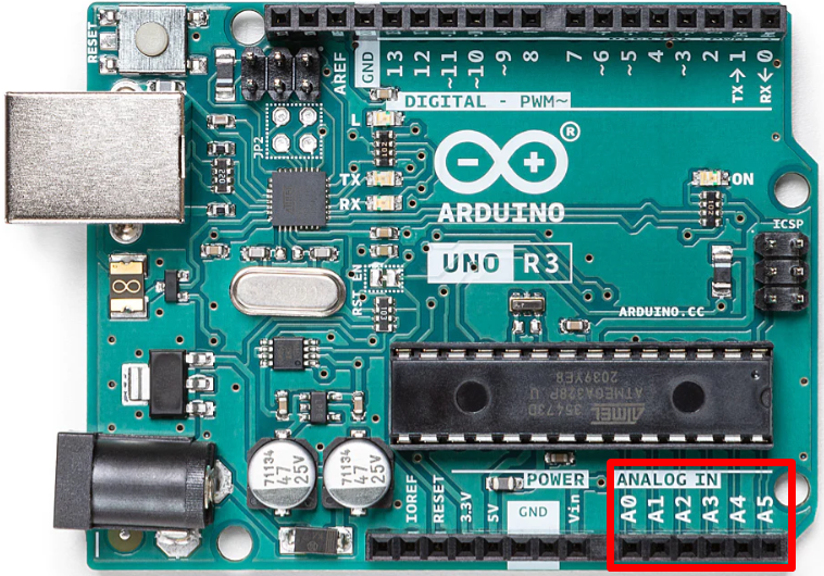
Analog pins vary from board to board. Arduino Uno has a total of 14 input output pins out of which 6 pins from A0 to A1 are analog pins. These pins can take analog data and using ATmega328p built-in Analog to Digital Converter (ADC) return digital values between 0 and 1023. Arduino has a 10-bit ADC which converts analog input to digital so they can be processed accordingly.
analogRead()
To receive analog signals, we use analogRead() function in Arduino programming. Most Arduino boards have analog pins from A0 to A5. These pins are designed to take input from Analog devices.
Syntax
Now we have covered the basic parameters of analog pins. Let’s see how we can use these analog pins as digital pins.
How to Use Analog Pin as Digital in Arduino
The main purpose of analog pins on Arduino boards is to read analog data coming from sensors and different modules. But in case if all digital pins are under use, we can configure these A0 to A5 pins as digital; it will work the same as digital pins 0-13.
Using the aliases technique, we can set any analog input pin as digital output. Code syntax will look like this:
digitalWrite(A0, HIGH);
Here we have mapped analog pin A0 as digital output and set its value to High.
digitalWrite() functions works on all pins including analog, with allowed parameters 0 or 1. digitalWrite(A0,0) will work exactly like analogWrite(A0,0), and digitalWrite(A0,1) is similar to function analogWrite(A0,255).
Analog pins can read/write analog values, like digital they don’t give a voltage output as 0 or 5, however they give a continuous range of voltage between 0 and 5.
Using analog pins, we can read/write analog values. Analog pins generally give us an output voltage between 0V and 5V, unlike the digital pins which give either a high that is 5V or low equal to 0V.
Analog pins generate an output voltage which looks continuous only when observed using a multimeter; however analog pins send signals of 0V and 5V to get output that looks like PWM.
Example: Controlling LED Using Arduino Analog Pin
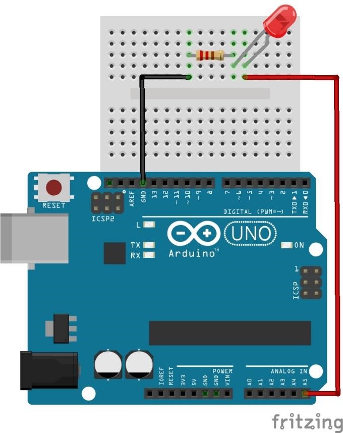
LED blink example is normally used with Arduino digital pins now we will control LED using analog pins with the method explained above. We will configure analog pin A5 as digital and let’s see what output comes. Connect a LED to pin A5 and GND of Arduino in between them a resistor is connected to maintain current safe limits.
Code
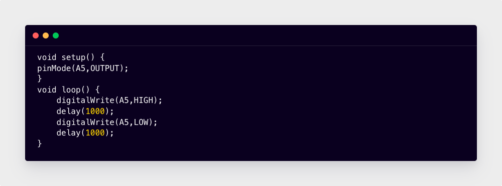
pinMode(A5,OUTPUT);
}
void loop() {
digitalWrite(A5,HIGH);
delay(1000);
digitalWrite(A5,LOW);
delay(1000);
}
Here in the above code, we have assigned analog pin A5 as digital output using the pinMode function. Using digitalWrite A5 is set HIGH for 1 sec after which it will become LOW for 1 sec. This cycle will keep on going as code is written inside the void loop.
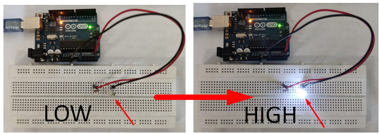
Output
Conclusion
Analog pin in Arduino can not only read continuous data but can also be configured as digital output. Using the pinMode function we can define any analog pin to use as a digital pin like any other GPIO pins. We have configured pin A5 in Arduino as digital and blinking a LED.