This article will explain the Arduino Nano Every pinout and their uses. You will also get information related to Nano Every power pins and its USB connector.
Table of Contents:
1. Arduino Nano Every Pinout
The Nano Every board is designed to be user-friendly, adaptable, and suitable for beginners and advanced Arduino users. With its small form factor and a weight of just 5 grams, it’s perfect for low-cost robotics and electronics projects.

The Arduino Nano Every contains the ATMega4809, a more powerful processor than the one in the Arduino UNO board. This allows you to compile a more advanced program, as it has 50% more program memory than the Arduino UNO ATmega328P. It also has 200% bigger RAM than UNO.
If you are using the Arduino Nano for your project, it will be a lot easier to swap it with your Arduino Nano Every board. Your code will work fine even after swapping both these boards, and you don’t need to rewrite those motors that you planned at the start of the project.
Before we proceed towards these details of each component of Arduino Every, below given table is a summary of all the main peripherals inside Arduino Nano Every board:
| Component | Description |
| Microcontroller | ATMega4809 |
| Working Voltage | 5V |
| VIN pin maximum volts | 7-21V |
| DC Current for single Input/Output Pin | 20 mA |
| Max current for 3.3V Pin | 50 mA |
| Microcontroller Clock Speed | 20MHz |
| CPU Flash Memory | 48 KB |
| SRAM | 6 KB |
| EEPROM | 256 bytes |
| PWM Pins | 5 (D3, D5, D6, D9, D10) |
| UART | 1 |
| SPI | 1 |
| I2C | 1 |
| Analog Input Pins | 8 (ADC 10 bit) |
| Analog Output Pins | Only through PWM (no DAC) |
| External Interrupts | all digital pins |
| LED Pin | 13 |
| USB Interface | Uses the ATSAMD11D14A |
| Length x Width | 45 mm x 18 mm |
| Weight | 5 grams including headers weight |
1.1. Microcontroller
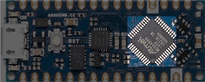
At the core of the Nano Every board we have the ATMega4809 microcontroller. This 8-bit AVR processor can run up to 20 MHz. It comes with 6 KB of SRAM, and a flash memory of 48 KB. It also has 256 bytes of EEPROM. These specifications make it able to handle more complex programs and large data arrays than its predecessors.
1.2. USB Connector
The Arduino Nano Every uses a Micro USB port for power and data exchange. This is an upgrade from the previous Arduino Nano, which comes with a Mini USB-B port. The Nano Every Micro USB connector supports 5V and can be used to power the board from different sources like a power bank and a PC USB port.
1.3. USB Bridge
For serial communication, Arduino Nano Every uses the SAMD11D14A processor. It comes with pre-installed firmware that enables a USB to the serial bridge and helps the firmware upgrade of the ATMega4809 via the UPDI interface. Additionally, this firmware also includes a bootloader, which helps the reprogramming of the processor to support various USB classes. This feature enhances the Arduino Nano Every functionality, which is generally restricted to only serial bridge functions.
Note: The pins of SAMD11D14A operate exclusively at 3.3V and connect to ATMega4809 through a level shifter. When connecting these pins to external circuits, extreme caution is necessary because they are not 5V tolerant.
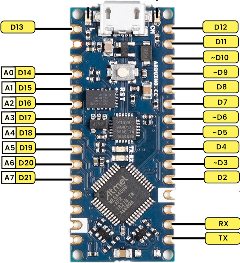
2. Pins
Arduino Nano Every pin is similar to Arduino Nano. There are a total of 30 pins in Arduino Nano Every. One main difference is PWM pins. Nano Every comes with one fewer PWM pins than the classic Arduino Nano which has a total of 6 PWM pins.
| Pin | Notation | Type | Description |
| 1 | D13 | Digital | Serves as SPI Clock (SCK) and a general-purpose I/O (GPIO) |
| 2 | +3V3 | Power Out | Supplies 3.3V power to external components |
| 3 | AREF | Analog | Provides a reference voltage for analog inputs; also functions as GPIO |
| 4 | A0/DAC0 | Analog | Acts as an analog-to-digital converter (ADC) input or digital-to-analog converter (DAC) output; usable as GPIO |
| 5 | A1 | Analog | Analog input channel; alternatively, a GPIO |
| 6 | A2 | Analog | Analog input channel; alternatively, a GPIO |
| 7 | A3 | Analog | Analog input channel; alternatively, a GPIO |
| 8 | A4/SDA | Analog | Analog input channel; I2C data line (SDA); also a GPIO |
| 9 | A5/SCL | Analog | Analog input channel; I2C clock line (SCL); also a GPIO |
| 10 | A6 | Analog | Analog input channel; alternatively, a GPIO |
| 11 | A7 | Analog | Analog input channel; alternatively, a GPIO |
| 12 | +5V | Power Out | Provides 5V power to external components |
| 13 | RST | Digital In | Reset pin, active low (same function as pin 18) |
| 14 | GND | Power | Electrical ground connection |
| 15 | VIN | Power In | Input voltage to the board |
| 16 | Tx | Digital | Transmission pin for USART; can function as GPIO |
| 17 | Rx | Digital | Receiver pin for USART; can function as GPIO |
| 18 | RST | Digital | Reset pin, active low (same function as pin 13) |
| 19 | GND | Power | Electrical ground connection |
| 20 | D2 | Digital | General-purpose I/O |
| 21 | D3/PWM | Digital | General-purpose I/O with PWM capability |
| 22 | D4 | Digital | General-purpose I/O |
| 23 | D5/PWM | Digital | General-purpose I/O with PWM capability |
| 24 | D6/PWM | Digital | General-purpose I/O with PWM capability |
| 25 | D7 | Digital | General-purpose I/O |
| 26 | D8 | Digital | General-purpose I/O |
| 27 | D9/PWM | Digital | General-purpose I/O with PWM capability |
| 28 | D10/PWM | Digital | General-purpose I/O with PWM capability |
| 29 | D11/MOSI | Digital | SPI Master Out Slave In (MOSI); also a GPIO |
| 30 | D12/MISO | Digital | SPI Master In Slave Out (MISO); also a GPIO |
Let’s discuss Arduino Nano Every pin in detail.
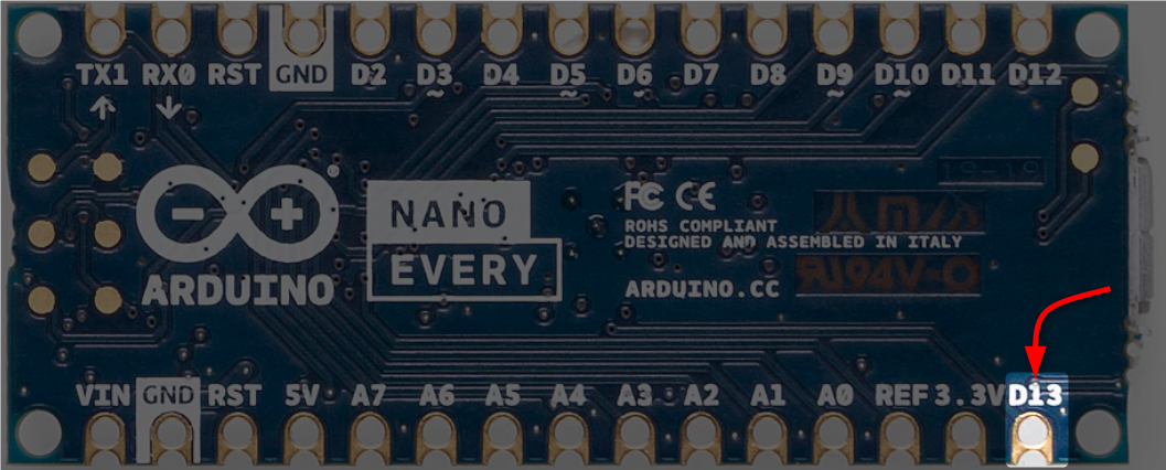
2.1. Built-in LED Pin
Arduino Nano Every has a built-in LED at pin D13 of the board. This pin also serves as an SPI Clock (SCK) and a general-purpose I/O (GPIO) pin.
2.2. Digital I/O Pins
Arduino Nano Every contains 22 digital I/O pins. Among these, there are five PWM pins. The description of each of these 22 pins is:
- D2 to D12: General-purpose I/O pins (Including five PWM pins D3, D5, D6, D9, and D10)
- D13: Serves as SPI Clock (SCK) and a general-purpose I/O (GPIO); also has a built-in LED
- Tx: Transmission pin for USART; can function as GPIO
- Rx: Receiver pin for USART; can function as GPIO
- Analog Pins: Eight analog pins which can also work as digital pins. These pins include (D14 (A0) — D21 (A7))
2.3. Analog Input Pins (ADC Pins)
Arduino Nano Every features eight analog pins that can be used as ADC (Analog to Digital). Using these analog pins, you can read analog sensor values and display them on Arduino IDE. These analog pins can also be used as digital input-output pins.
Analog pins include:
- A0 to A7: Analog input channels
- AREF: Provides a reference voltage for analog inputs; also functions as GPIO

2.4. PWM Pins
Arduino Nano Every features one fewer PWM pin than the classic Arduino Nano board. Arduino Nano Every has a total of five PWM pins. These pins are D3, D5, D6, D9, and D10.

3. Communication
Arduino Nano Every has different communication protocols. These protocols include the UART, I2C, and SPI protocols. Below is the detail of each protocol and their respective pins in Arduino Nano Every board.
3.1. UART
According to the datasheet, Arduino Nano Every processor has four USART (Universal Asynchronous Receiver-Transmitter) interfaces. These UARTs allow asynchronous serial communication among devices. However, by default, the Nano Every only exposes two of these UARTs:
- Serial: This is the primary UART used for communication with the computer via USB.
- Serial1: This is an additional UART available on the Nano Every. This UART is accessible through Tx and Rx pins.
The other two UARTs are not directly exposed by default. You can enable them by modifying the pins_arduino.h file in the code files for the Nano Every board.
UART pins of Arduino Nano Every
- Tx (Pin 16)
- Rx (Pin 17)

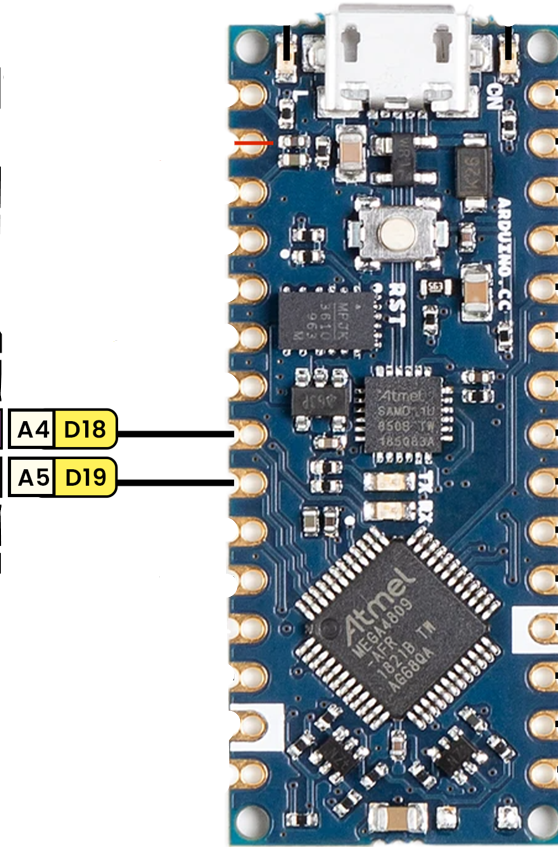
3.2. I2C
I2C or (Inter-Integrated Circuit) protocol can be used for communication between multiple devices over two wires SDA and SCL. Each of the devices connected over the I2C protocol has its unique address to get recognized by the Master (Arduino board).
In Arduino Nano Every, the I2C pins are A4 and A5. These pins can also function as GPIO pins.
- A4/SDA: I2C data line (Pin 8)
- A5/SCL: I2C clock line (Pin 9)
3.3. SPI
SPI is a synchronous serial data protocol. It is a high-speed communication protocol. Most SPI applications are for short-distance communication.
Following are the SPI pins in Arduino Nano Every:
- D11 (COPI): SPI Master Out Slave In (MOSI)
- D12 (CIPO): SPI Master In Slave Out (MISO)
- D13 (SCK): Serves as SPI Clock (SCK)
- CS: Use any GPIO for Chip Select (CS).

NOTE: CIPO/COPI were formerly known as MISO/MOSI
4. Power
Arduino Nano Every operates at 5V and can be powered either using a Micro USB port or using the VIN pin. The VIN pin supports a voltage range of 7V–21V. The board also has a power LED that lights up as soon as the board is connected to the power source.
Following are the main power pins of Arduino Nano Every board:
- VIN: This pin can supply power to the board with an external power source. As mentioned, 7V–21V is the safe range.
- 5V: This pin outputs 5V which is coming from the voltage regulator.
- 3V3: A 3.3V supply is generated by the onboard regulator.
- GND: Ground pins.
Following are some safe current limits for the Arduino Nano Every board:
- Maximum current per pin is limited to 40mA, but it is recommended not to give more than 20mA.
- The maximum current the entire board package can handle is 200mA.
- Ensure that the total current for each power group of ports stays under 100mA.
- The maximum current for the 3.3V Pin is 50 mA.
4.1. Power Converter
Two main power converters are the lifeline for Arduino Nano Every board. One is the DC-DC step-down converter, which converts the incoming voltage from the VIN pin to the recommended 5V. The second power converter is the LDO regulator used for 3.3V pin output.
- MPM3610 (DC-DC): This converter regulates voltages up to 21V. It has a minimum efficiency of 65% at the lowest load. It archives over 85% efficiency when the input is at 12V.
- AP2112K-3.3 (LDO): This regulator steps down input voltages from 5V to 3.3V, providing up to 550mA of output current for user applications. The recommended optimal range of current for this regulator is a maximum of 200mA.
4.2. Power Tree
The power tree for Arduino Nano Every illustrates how the power is given to the board and the ATMega4809 microcontroller.
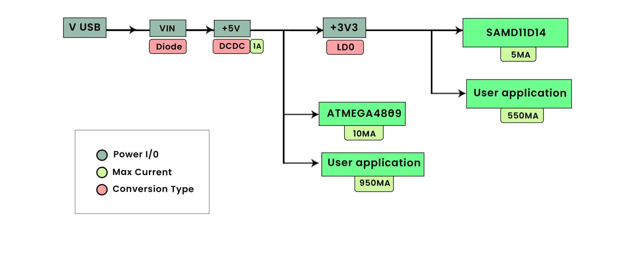
The Arduino Nano is designed to be flexible in terms of power supply. The Nano Every can be powered directly via the USB connection. When not using USB, an external power source can be connected to the VIN pin. The 5V pin provides the regulated 5V output from the onboard regulator. The board also includes a 3.3V regulator to provide the 3.3V at the 3V3 pin.
Note: The voltage from the USB port is given to the VIN pin after passing it from the Schottky diode and DC-DC regulator. Due to losses in the diode and regulator, the minimum voltage required for board function is 4.5V while powering through the Micro USB port. The recommended range is between 4.8V and 4.9V, depending on the required current.
5. RESET Pins
Arduino Nano Every features two REST pins at pin 13 and pin 18. Both these pins can reset the microcontroller. When any of these pins are brought to LOW, it triggers the rest of the ATMega4809 processor.

6. Debug Connector
Beneath the communication module on the board’s underside, debug connectors are organized into a 3×2 array of test pads. These debug connector pins are 100mil apart, with the fourth pin omitted.
Here is the description of these debug connectors:
| Pin | Function | Type | Description |
| 1 | +3V3 | Power Out | This pin provides a 3.3V power supply from the board |
| 2 | SWD | Digital | SWDIO (Serial Wire Debug Data I/O) is used for bidirectional data transfer in debugging |
| 3 | SWCLK | Digital In | SWCLK (Serial Wire Debug Clock) provides the clock signal for the Serial Wire Debug interface |
| 5 | GND | Power | Ground pin |
| 6 | RST | Digital In | Rest pin |

7. Dimensions
The Arduino Nano Every board measures 45 mm in length and 18 mm in width. It weighs 5 grams only. With its compact size, it’s best for wearables and drone projects.
Arduino Nano Every board dimensions:
- Weight: 5 grams
- Width: 18 mm
- Length: 45 mm
8. Pricing
The Arduino Nano is available at different prices, varying according to quantity. If you buy a single board it will cost you around 14 USD, or if you go with the Arduino Nano Every pack you can get three Nano Every for 39 USD, saving you 1 USD per board.
If you are on a tight budget you can explore the Chinese alternative Arduino Nano Every which will cost you a max of 5 USD. You will hardly notice any difference between the official Nano Every and the one you got from the Chinese manufacturers.
Conclusion
The Arduino Nano Every is the updated version of the classic Arduino Nano board. With this new board, you get a package with a balance between the performance, cost, and form factor. Due to these factors, it’s an ideal choice for less-space projects. With the new ATMega4809 microcontroller, you get 50% more program memory than the Arduino UNO ATmega328P. It also has 200% bigger RAM than UNO. With one fewer PWM pins than the classic Arduino you get the complete package with UART, I2C, and SPI protocols. You can get more insight into this board in this article.