How to Simulate Arduino in Proteus
Proteus is an electronic simulation and designing tool developed by Lab Center Electronics. It ensures that circuit design and code is working properly before we continue to do physical work.
One of the main highlights of Proteus is it supports Arduino simulation. Due to its extensive collection of libraries it’s one of the favorite tools in the Arduino community and not only that, Proteus can also design customized PCB for Arduino projects.
To simulate Arduino with Proteus we need following tools:
Follow the steps given below to simulate Arduino using Proteus.
Installing Arduino Libraries in Proteus
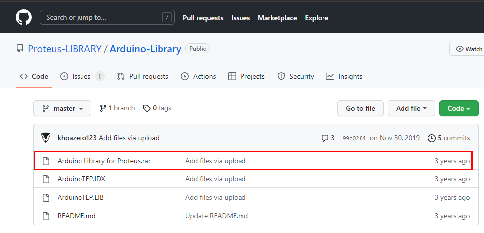
Step 1: To start with Proteus first we have to install Arduino libraries in Proteus. Most of the updated Proteus versions have pre-installed Arduino libraries. In case of the older version click here to download Arduino libraries for Proteus.
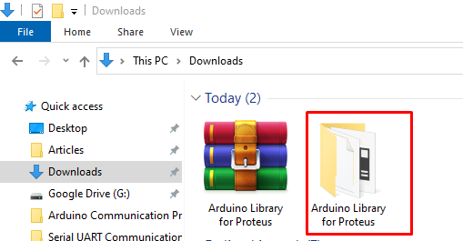
Step 2: Once the Arduino libraries are downloaded, open the Download folder and extract the Libraries file into a new folder or directory.
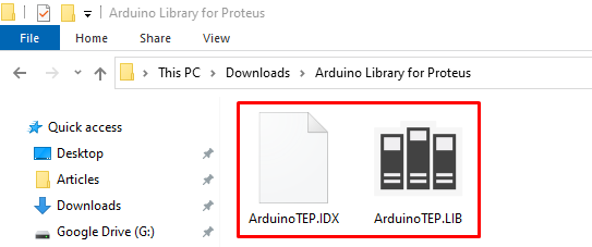
Step 3: Now open the extracted folder and copy both Arduino libraries file with extension “.IDX” and “.LIB’’.
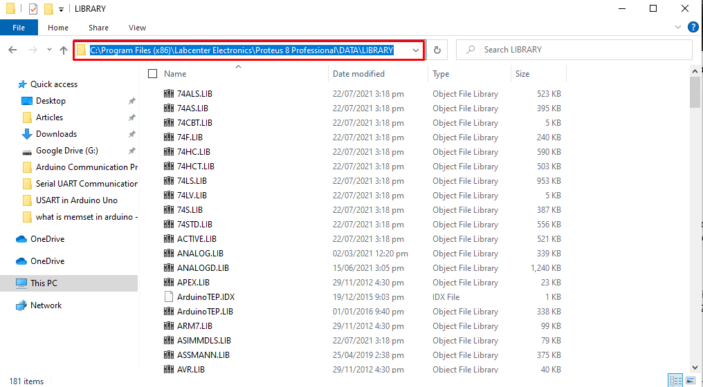
Step 4: Once Arduino libraries files are copied head towards the Proteus library directory or type the below given folder address bar.
C:\Program Files (x86)\Labcenter Electronics\Proteus 8 Professional\DATA\LIBRARY
Now paste both files copied earlier in this folder.
We have completed the Arduino Libraries installation in Proteus. Now we will move towards Arduino circuit design in Proteus.
Create New Project in Proteus
After successful installation of libraries, the next step is to create a new project in Proteus.
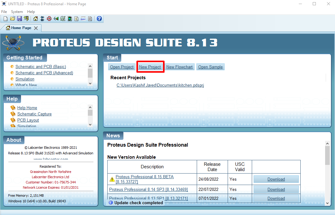
Step 1: Open Proteus and create a new Proteus project.
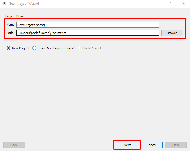
Step 2: New window will open here we can name Proteus project and set destination folder for Proteus file. Click Next to continue.
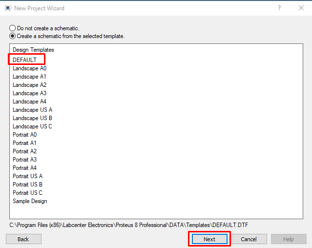
Step 3: Now select schematic layout for Proteus project. We will go with default settings.
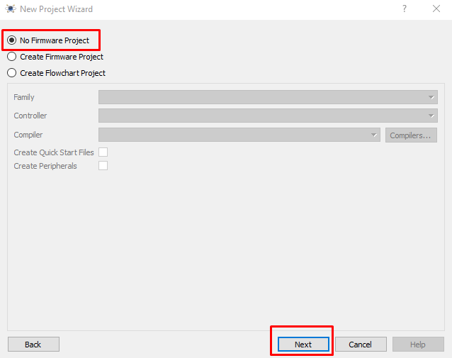
Step 4: Next select no firmware project, as we only need to simulate a simple program so there is no need to create a firmware project. Click Next to continue.
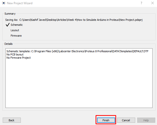
Step 5: Recheck all the selected settings and click finish to open Proteus project.
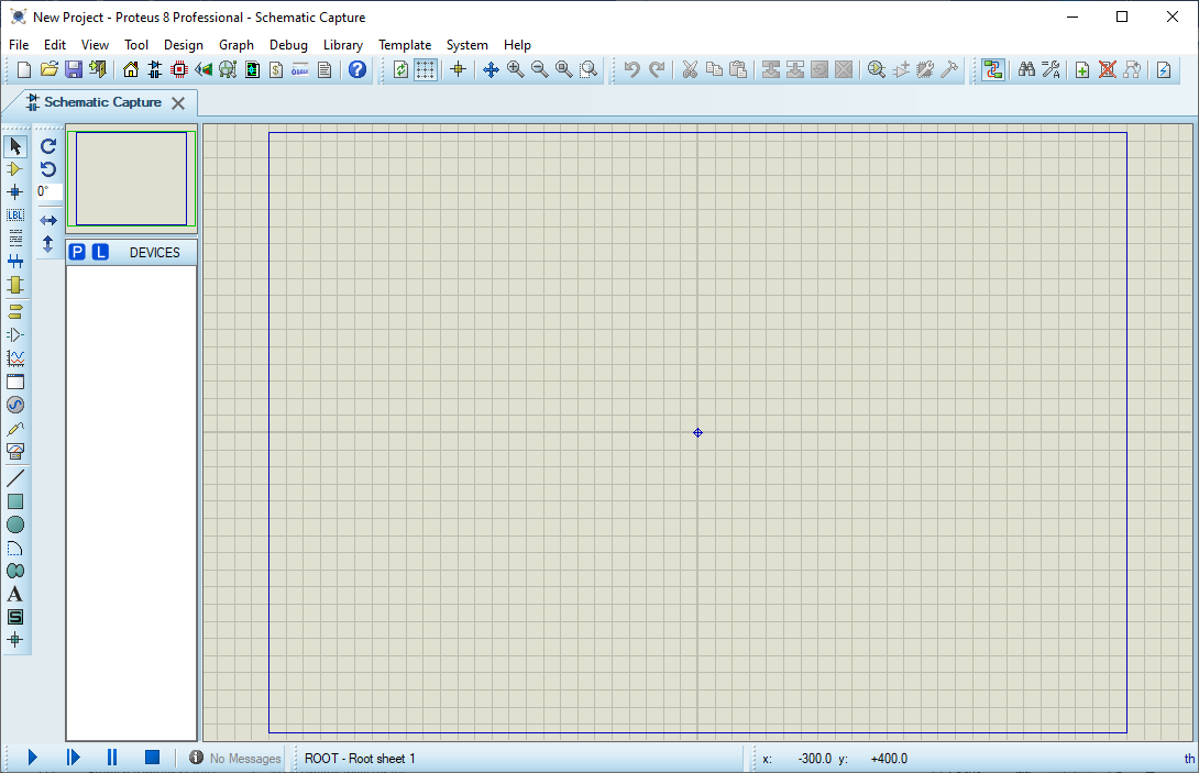
Step 6: A new window will open showing us the Proteus interface. Here we can design an Arduino project and simulate it to see output.
Design Arduino LED Blinking Circuit in Proteus
Once a new project is created successfully in Proteus, now we will design an Arduino circuit for blinking LEDs in Proteus.
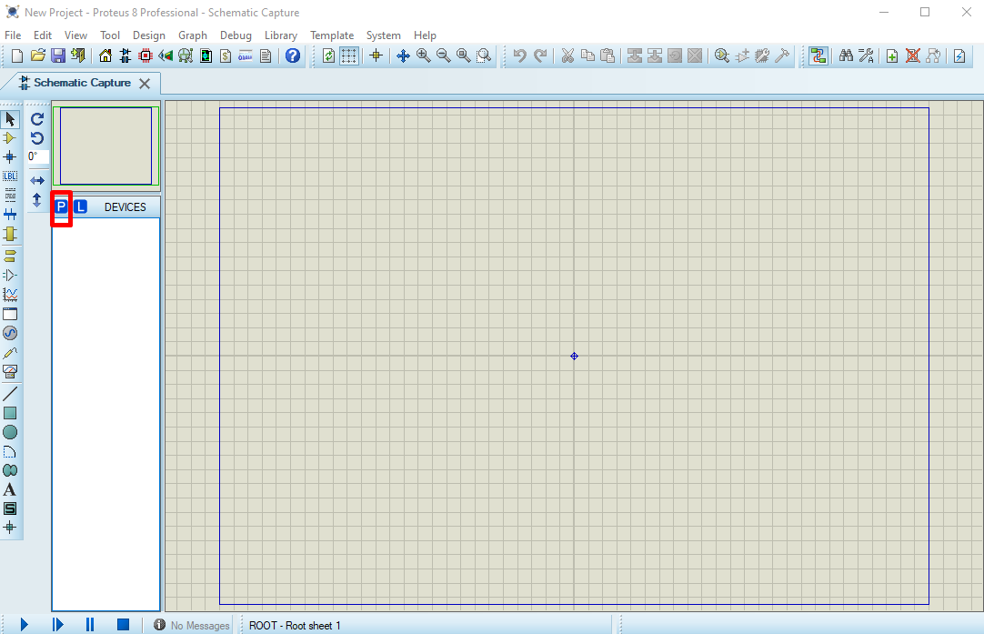
Step 1: Click the P label as shown in figure below. Here P denotes Pick Devices. From this section we can add any hardware module, Arduino boards and sensors into the Proteus project.
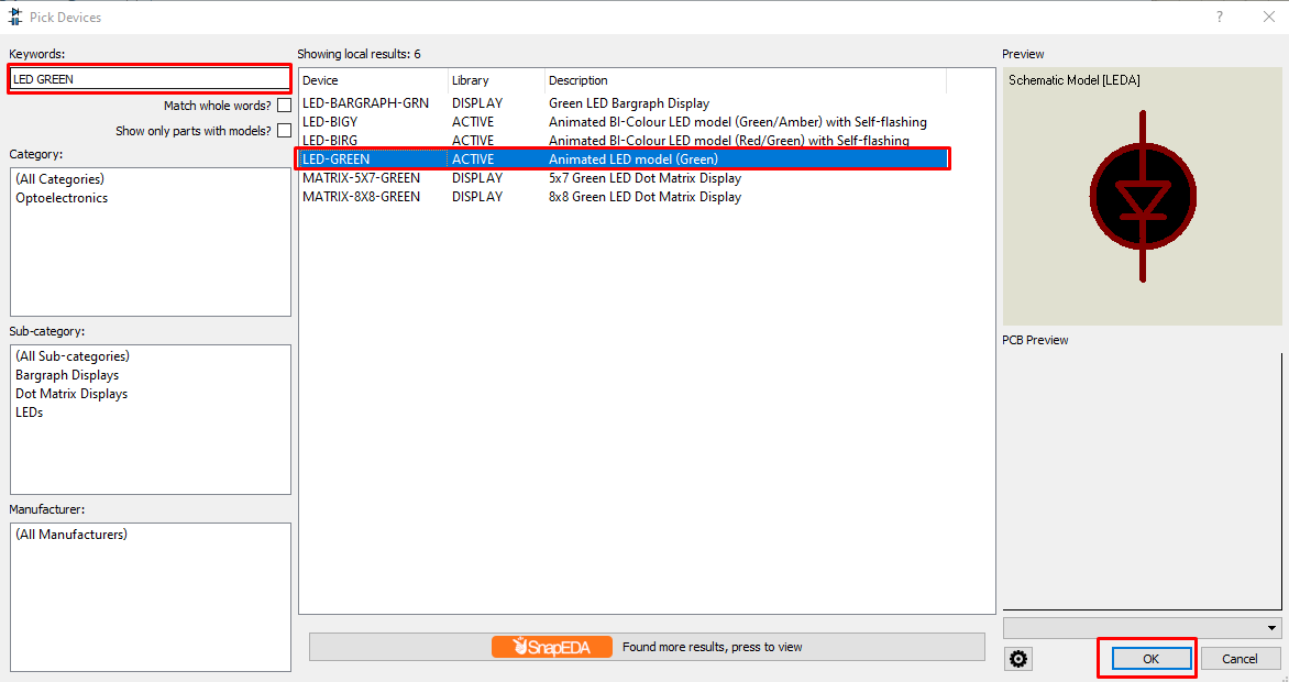
Step 2: New window will open where we can add components required to build Arduino LED blinking simulation. Type keywords related to components. First, we will add a Green LED to the project. Select LED and click Ok.
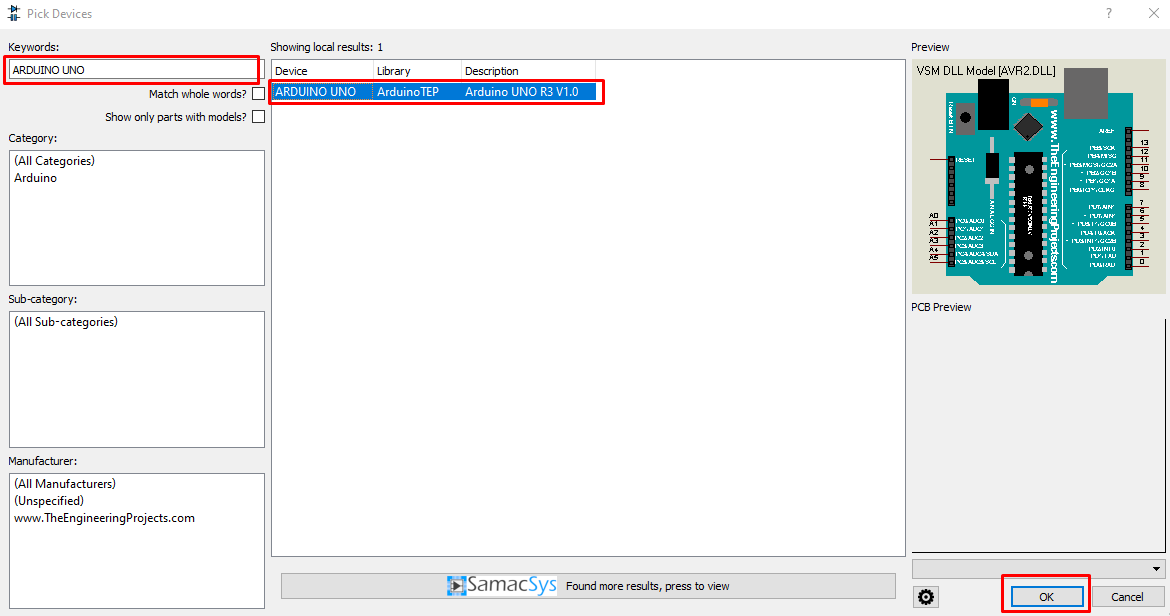
Step 3: Just like the previous step, now search for Arduino UNO board, Select Arduino board and click Ok to add in project, alternatively double click to add Arduino in Proteus project.
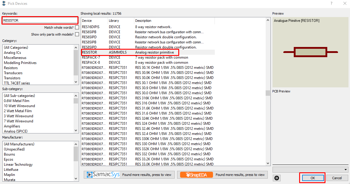
Step 4: Last component which is required is a resistor that will maintain a safe current limit between Arduino and LED.
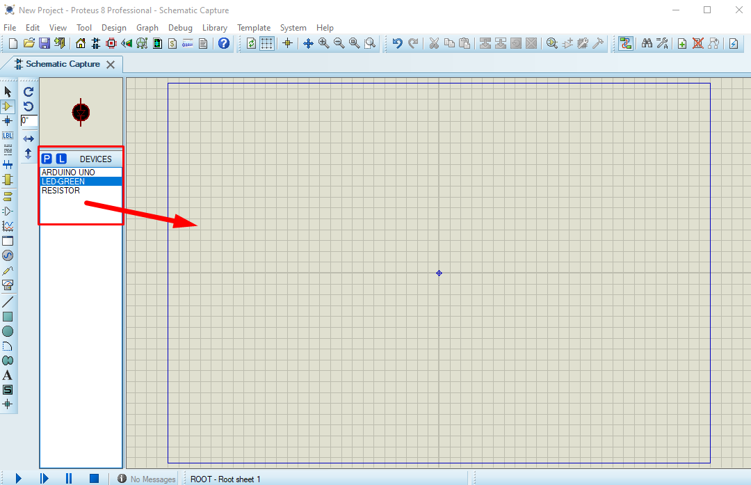
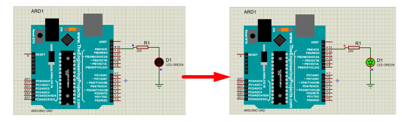
Step 5: After adding all the components, select components one by one from the Devices menu and arrange them in the Proteus project.
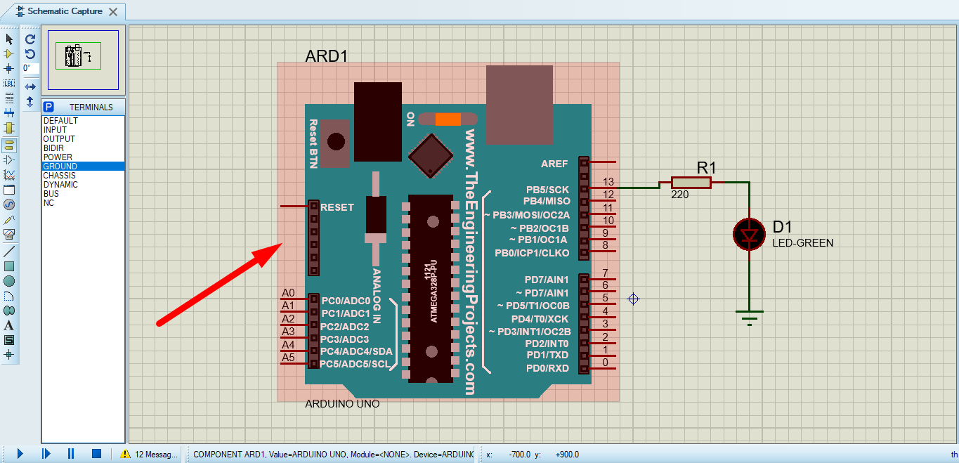
Step 6: Another important terminal required is Ground block. Proteus has a separate terminal block from where we can get Ground terminal for the Proteus project.
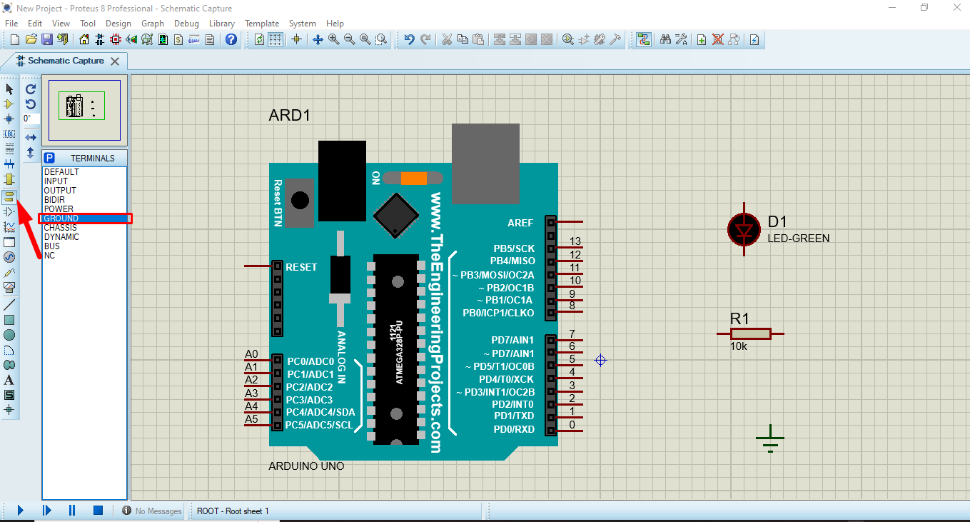
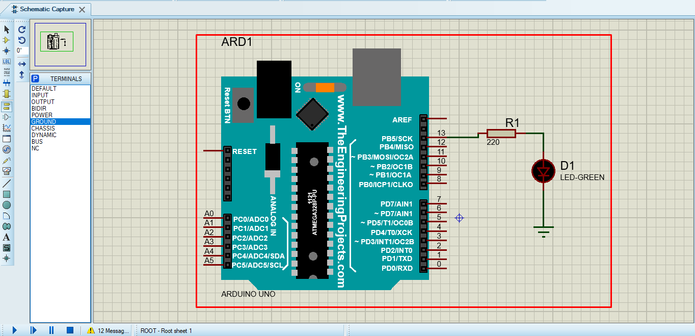
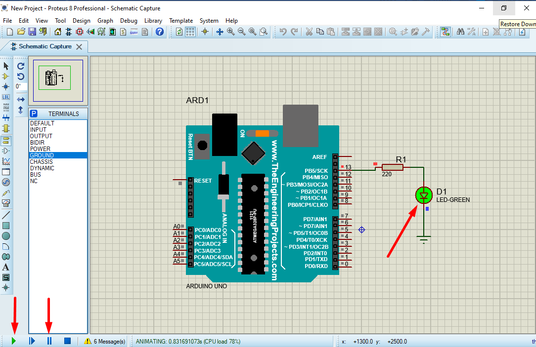
Step 7: Arrange all the components as shown in figure below. Connect positive leg of LED to pin 13 of Arduino and negative Leg with GND. In between Arduino and LED connect a resistor.
Remember to change the value of the resistor to 220ohm otherwise LED will not operate.
Uploading Hex File from Arduino IDE to Proteus
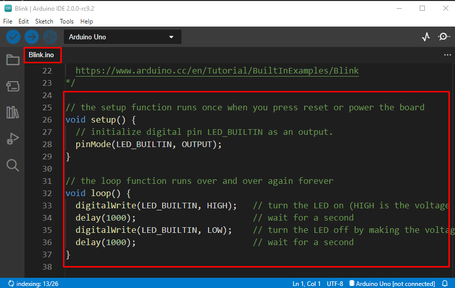
Step 1: After designing the Arduino circuit in Proteus now open Arduino IDE. Open an example sketch of LED blinking from the IDE examples section. Go to: Files>Examples>Basics>Blink
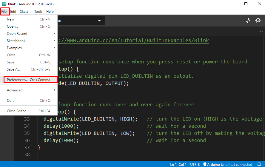
Step 2: To simulate the Arduino program in Proteus we need a Hex file. To get Hex file location follow below steps.
Go to: File>Preferences or Press Ctrl + comma.
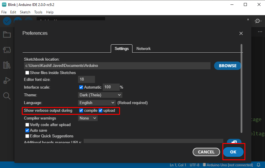
Step 3: A new window will appear, head towards the Verbose output section and check compile and upload options. After selecting click Ok. Doing this will give us the Arduino Hex file location in the Output window of IDE.
Step 4: Compile the LED blinking program from the quick action button.
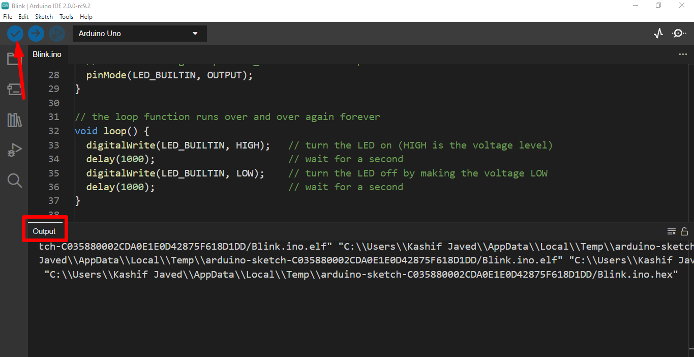
Step 5: In the output window look for the “.hex” file of the compiled Arduino program.
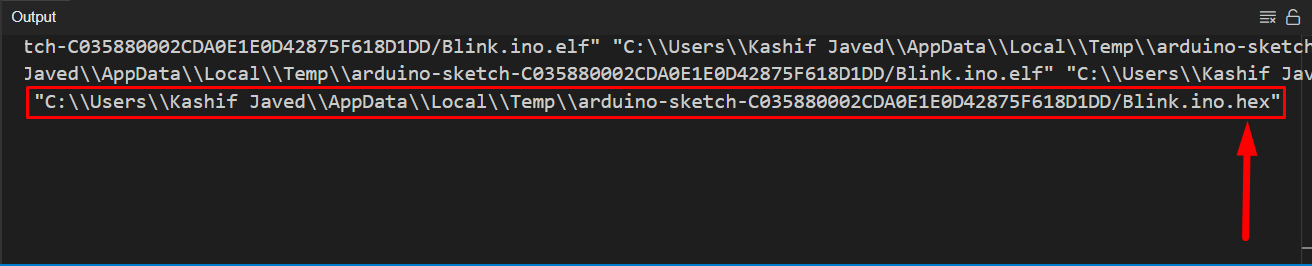
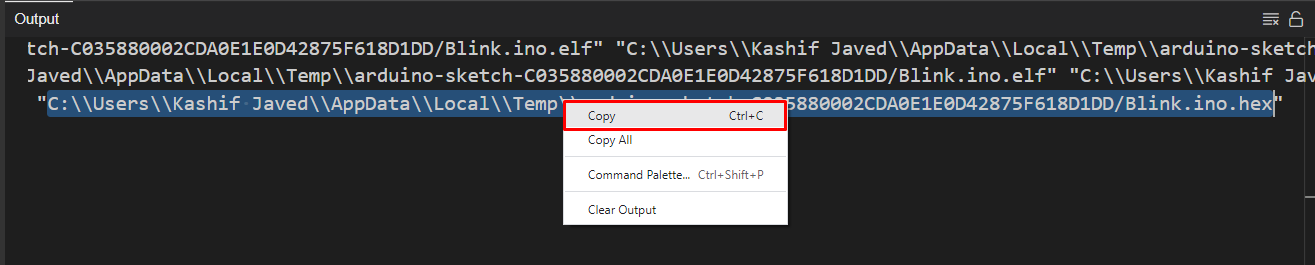
Step 6: Copy the path to the Hex file.
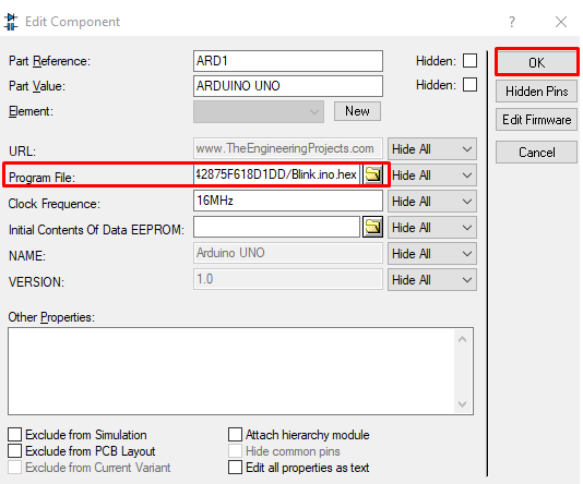
Step 7: Open Proteus again and double click the Arduino board.
Step 8: A separate window will open, look for the Program File and paste the Hex file address copied earlier from the Arduino IDE output section and click Ok.
Step 9: Arduino Hex file is uploaded inside the Proteus Arduino model. Now click the Play button at bottom left, LED will start blinking. To stop the simulation use the pause button present just right to the play button in the bottom left of the screen.
Step 10: LED will start blinking in a cycle of 1 sec off and 1 sec on.
We have completed Arduino simulation using Proteus. An LED blinking example is used in creating this Arduino model in Proteus.
Conclusion
Proteus is a great tool for simulating electrical projects. Here we have covered how we can simulate an Arduino program using the Proteus model. The LED blinking model is designed using Proteus. Further Proteus can be used to design any Arduino related project, it will give better understanding before moving to hardware level.