To cater for such issues shift registers can be used that can save the pins of Arduino board for other devices. We have discussed how we interface the 7-segment with Arduino using the shift register.
7 segments with Arduino using the shift register
As explained earlier shift registers come in handy when the number of devices that are to be interfaced with the microcontroller is large. To interface the 7-segment with Arduino using the shift registers you will be requiring the following components:
- 7-segment display
- Breadboard
- Arduino Uno
- Connecting wires
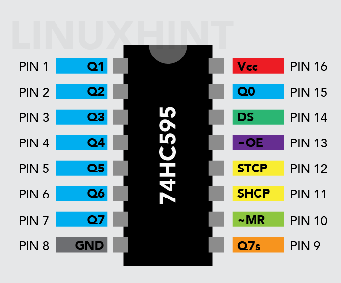
- 74HC595 shift register
- 7 220-ohm resistors
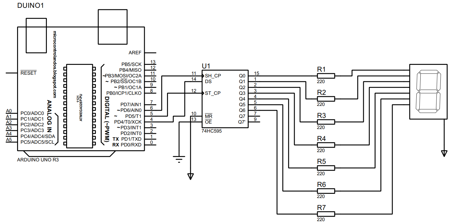
To use the shift register for interfacing the 7-segment with Arduino Uno we have designed a circuit whose schematic is given below that is using the list of components given above.
Hardware assembly for using the shift register with Arduino for 7-segment display
Before implementing the circuit on the actual hardware, we have created the hardware assembly that will help in making connections of the components on the actual hardware. Below the given image shows the hardware assembly for using the shift register with Arduino to interface the 7-segment with it.
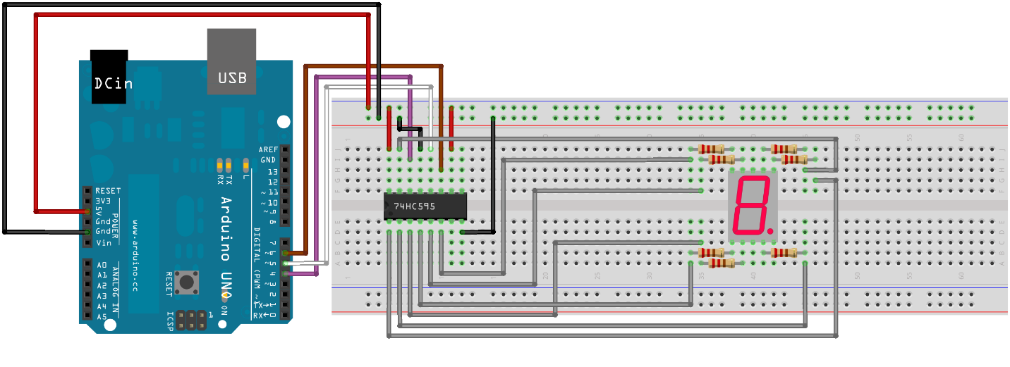
The connections for the 7 segments with shift register is quite simple if you follow the pin numbers of the shift register. We have explained connections of the circuit in the following points:
- To connect the 7-segment with shift register we have connected the pin “a” of 7-segment with pin 15 and continue connecting the pins in the alphabetic order up to “g” using the gray wire.
- To connect the data pin of the shift register with Arduino Uno we have used the purple wire that connects to pin 4 of the Arduino.
- We have used the white wire to connect the latch pin of the shift register with Arduino Uno using its pin 5.
- The brown wire is used to connect the latch pin of the shift register with Arduino Uno using its pin 6.
- For powering the circuit, we have used the 5-volts supply from the Arduino Uno and the connections are represented by the red and black wires.
Arduino program for using the shift register to interface 7-segment with Arduino Uno
To interface the 7-segment with Arduino using the shift register we have to program the microcontroller that is given below:
const int latch = 5; // Arduino pin for latch pin of the shift register
const int clock = 6; // Arduino pin for clock pin of the shift register
const char common = 'c'; // 7-segment with common cathode
void setup() {
// assigning the working modes to the shift register pins
pinMode(data, OUTPUT);
pinMode(latch, OUTPUT);
pinMode(clock, OUTPUT);
}
void loop() {
for (int i = 0; i <= 9; i++) {// for loop to generate number from 0 to 9
byte bits = binary(i) ; /* detect the binary given for respective number from the cases given below */
display(bits); // displaying the numbers on 7-segment
delay(500);
}
}
void display(byte eightBits) {
if (common == 'c') { // if the configuration is common cathode
eightBits = eightBits ^ B11111111; // then change the bits from 0 to 1
}
digitalWrite(latch, LOW); // preparing shift register for data
shiftOut(data, clock, LSBFIRST, eightBits); /* sending the data to 7segmnet starting from least significant bit*/
digitalWrite(latch, HIGH); /* displaying the data on the 7 segment */
}
/*cases for detecting the binary of the numbers generated from 0 to 9 */
byte binary (int Number) {
switch (Number) {
case 0:
return B11111100;// if 0 is generated then binary for zero
break;
case 1:
return B01100000;// if 1 is generated then giving binary for one
break;
case 2:
return B11011010;// if 2 is generated then giving binary for two
break;
case 3:
return B11110010;// if 3 is generated then giving binary for three
break;
case 4:
return B01100110;// if 4 is generated then giving binary for four
break;
case 5:
return B10110110;// if 5 is generated then giving binary for five
break;
case 6:
return B10111110;// if 6 is generated then giving binary for six
break;
case 7:
return B11100000;// if 7 is generated then giving binary for seven
break;
case 8:
return B11111110;// if 8 is generated then giving binary for eight
break;
case 9:
return B11110110; // if 9 is generated then giving binary for nine
}
}
By controlling the latch pin of the shift register we can send the data from Arduino to the 7-segment. So, when the latch pin is in LOW state it receives the data and then when the pin goes in HIGH state it sends the data further.
For generating the numbers, we have used the for loop and at each iteration of the loop the latch pin state is changed using the digitalWrite () function and for each number we have given the binary for it that will turn on the LED of the 7-segments accordingly.
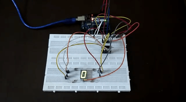
Hardware demonstration for using shift register with Arduino to interface the 7-segment
We have implemented the circuit on the breadboard to interface 7-segments using a shift register with Arduino Uno according to the hardware assembly that we have described earlier. To demonstrate we have given the animated gif below:
Conclusion
The shift registers are of great importance in the projects where there are a large number of devices to be used with Arduino. We have interfaced the 7-segment display with Arduino using a shift register that reduces the usage of Arduino pins from 6 to 3. We have also provided the circuit schematic, hardware assembly and Arduino code that will help you in understanding the concept of using the shift register.