UART is an acronym of Universal Asynchronous Receiver-Transmitter. UART is the most used serial communication protocol in which data format and communication speed is configurable. Arduino has three communication protocols named SPI, I2C and UART. UART protocol allows Arduino to communicate between different devices and sensors. Now we will discuss how to use UART communication between two Arduino boards.
Serial UART Communication
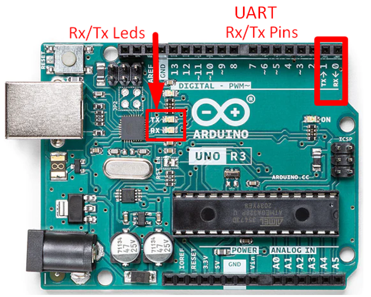
Serial UART is the serial communication protocol used by Arduino to communicate with microcontrollers and PCs. Arduino has one UART port at D0 and D1. A serial bus with two terminals is used in UART communication, one for sending data named Tx at pin D1 and another one for receiving data which is denoted as Rx at pin D0. So, all the devices that works over UART protocol must have two serial pins:
- Rx for Receiving data
- Tx for Transmitting data
While using these two pins for UART It’s important to note that UART pins are specific for a device itself means if you want to establish serial communication using UART between two Arduino boards then the Rx pin of first board will be connected to the Tx pin of second board similarly Tx pin of first one with Rx pin of second one.
UART Serial Communication between Two Arduino Boards
Now, we will connect two Arduino boards using Tx and Rx pins to establish a serial communication between them one Arduino board which will transmit data will act as a Master and the second Arduino board which will receive instructions will act as Slave. We will setup our Arduino boards in Master and Slave configuration. Before going further, we need the following equipment to start our UART serial communication.
Equipment Required
- 2x Arduino Boards
- 2x USB B cable
- 6x Jumper wires
- Breadboard
- Resistor 220 Ohm
- LED
To start communication between two Arduino boards, one will be configured as Sender and other Arduino board as the receiver. So, we must write two programs, one for sender and second for receiver. Follow the below mentioned steps to establish serial communication.
Example 1: Passing a String from One Arduino to Other through UART Communication
We will define a string in our Master Arduino and will try to pass it to Slave Arduino using UART serial communication. Follow below given steps to pass data between two Arduinos.
Step 1: Connect Master Arduino
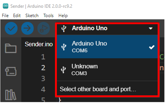
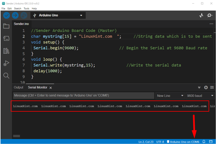
Using a USB B cable connects the Arduino board which is acting as Master to the PC. Remember to select the COM port first before uploading the sketch. Here in our case the Arduino is connected at COM6 port.
Now upload below code to the sender Master Arduino board.
char mystring[15] = "LinuxHint.com "; //String data which is to be sent
void setup() {
Serial.begin(9600); // Begin the Serial at 9600 Baud rate
}
void loop() {
Serial.write(mystring,15); //Write the serial data
delay(1000);
}
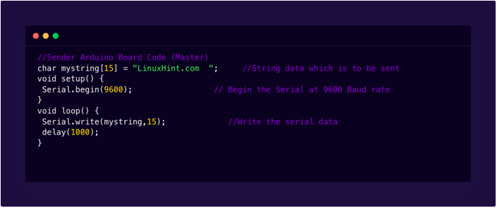
Above code will send a simple message LinuxHint.com to the other Arduino. First, we have defined an array “LinuxHint.com”. The number 15 inside brackets shows that this array can hold 15 characters. 13 are alphabets while 2 are set for space so that we can see clear output in the serial monitor. Inside setup() serial communication is established using Serial.begin() and 9600 is selected as baud rate.
The loop() section of the sketch contains the Serial.write() function. These functions will write a message to the receiver Slave Arduino board with 1000 milliseconds delay.
Step 2: Connect Slave Arduino
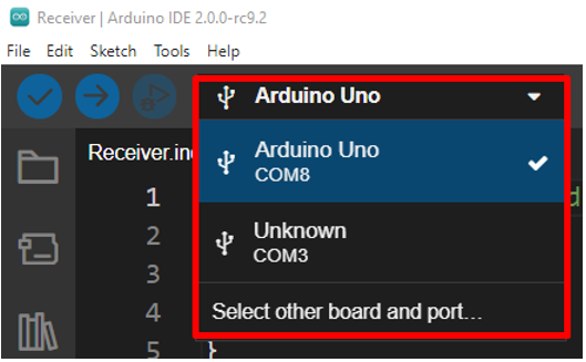
Connect the second Arduino board which is Slave in our configuration. Connect this board at any PC port other than the port used in the previous step by the Master Arduino board. Before uploading the Arduino code select Arduino COM port. Our Slave Arduino board is connected at COM8.
Now upload below given code in Slave Arduino board.
char mystring[20]; //Initialized variable to store receive
void setup() {
Serial.begin(9600); // Begin the Serial at 9600 Baud
}
void loop() {
Serial.readBytes(mystring,15); //Read the serial data
Serial.println(mystring); //Print data on Serial Monitor
Serial.println(" RECEIVER");
delay(1000);
}
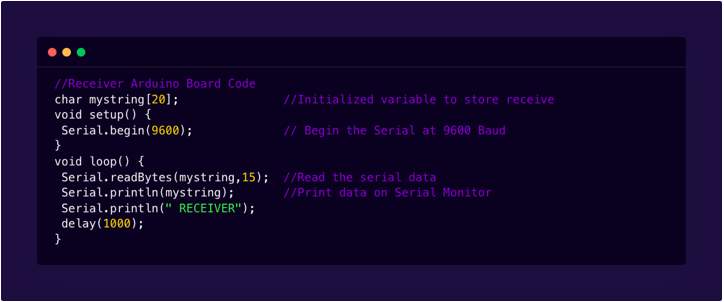
Above code of Slave Arduino is similar like Master Arduino only difference is here instead of Serial.write() we have used Serial.readBytes() which will read incoming data from Master Arduino. After reading data I will be printed on the serial monitor using Serial.println() function.
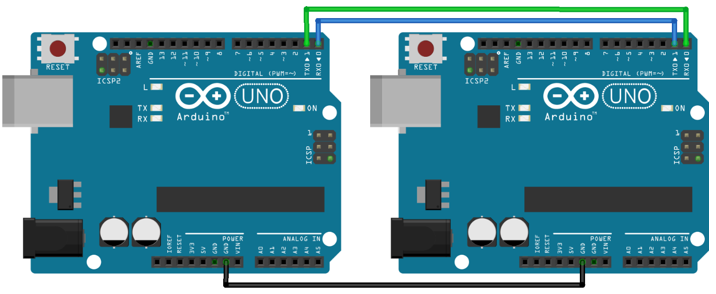
Step 3: Connect Both Arduino Using TX and Rx Pins
Once Arduino code is uploaded in both Arduino boards now connect Master and Slave Arduino board as shown in figure below. Connect Tx pin of first Arduino with Rx pin of second Arduino similarly Rx pin of first Arduino with Tx pin of second Arduino.
Remember while uploading code in both these Arduino do not connect Tx and Rx pins otherwise serial communication will not be possible.
Output of Master Arduino
Master Arduino is sending a string constantly to Slave Arduino with a delay of 1000 milliseconds.
Output of Slave Arduino
Slave Arduino will first print RECEIVER in output serial terminal after that it will receive an array LinuxHint.com with a delay of 1000 milliseconds from Master Arduino. Hence serial communication is done between two Arduino boards.

Example 2: Blink LED Using Two Arduino Boards through UART Communication
Step 1: Upload Code to Master Arduino Board
Connect the Arduino board which is acting as Master with the PC using USB B cable and select the COM port at which Arduino is connected. In our case the Master Arduino board is connected at the COM7 port.
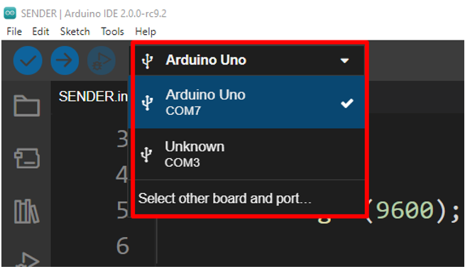
Upload the given code below in the Sender Arduino board.
void setup()
{
Serial.begin(9600);
}
void loop()
{
Serial.print(1);
delay(2000);
Serial.print(0);
delay(2000);
}
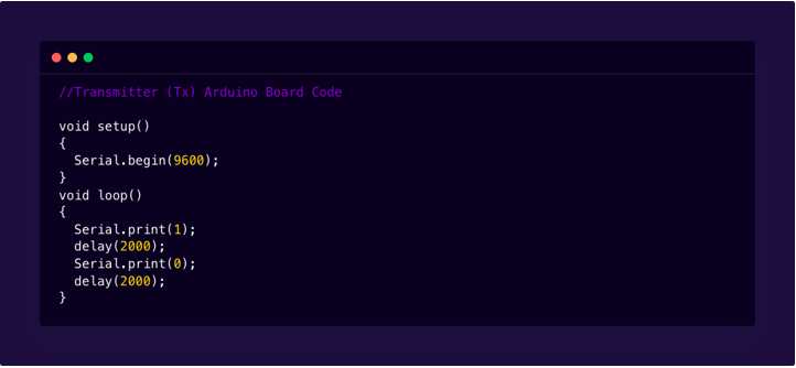
In above code Master Arduino is sending instructions to Slave Arduino in the form of numbers 1 and 0. Master sends number 1 then waits for 2 seconds after that it sends number 0 then again goes for a delay of 2 seconds. After that it starts repeating in a loop. Here we have used the Serial.print() function which will convert Master Arduino instructions into ASCII characters which means master will transmit values 49 for 1 and 48 for 0.
Step 2: Upload Code to Slave Arduino Board
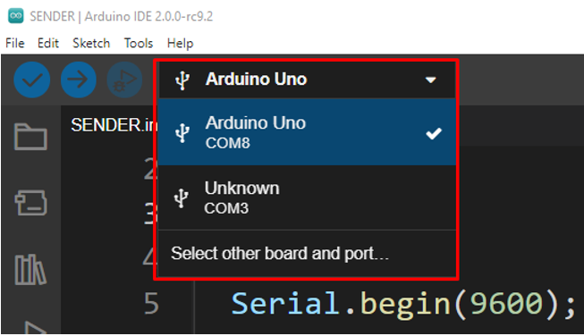
Now Connect second Arduino board which is acting as Slave with any other port of PC using USB B cable. Remember to select the Arduino board COM port first before uploading sender code. Slave Arduino board is connected at COM8 port of PC.
Now upload the below code in second Arduino board which is acting as slave.
char serialinput = ' ';
byte LED = 2;
void setup()
{
pinMode(LED, OUTPUT);
Serial.begin(9600);
}
void loop()
{
if(Serial.available())
{
char serialinput = Serial.read();
if (serialinput =='0') { digitalWrite(LED, LOW); }
if (serialinput =='1') { digitalWrite(LED, HIGH); }
Serial.println(serialinput);
}
}
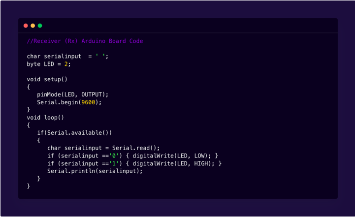
In above code of Slave Arduino char serialinput is initialized which will receive and store instructions coming from Master Arduino.
After that in the loop section of code a check will be made using if condition.
Above command will check whether there is any data coming in the buffer or not.
If there is any data coming a single character is read and stored in char variable serialinput.
Since we are interested in 0 and 1 values only. If statements will do the work here. If statements will check the serialinput value if it is 1 it will send high signal to LED connected at pin 2 of Slave board. If it received serialinput 0 it will send a Low signal to pin number 2.
Note: Always connect both Arduino boards at separate COM ports and before uploading new code select Arduino COM port first. It’s recommended to use two separate windows of IDE for both Arduino boards.
Step 2: Upload Code to Slave Arduino Board
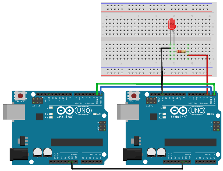
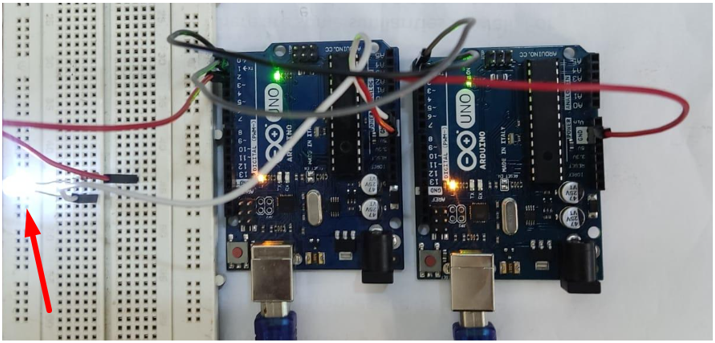
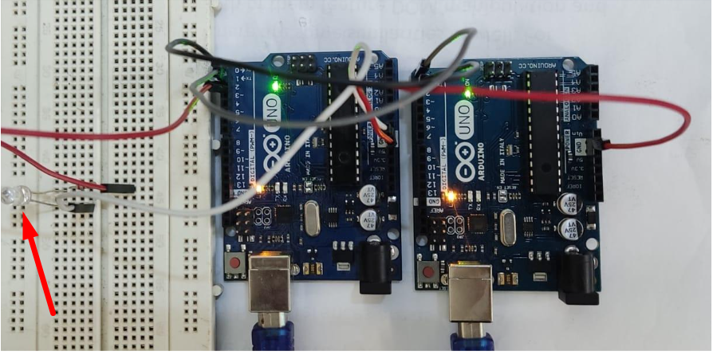
Connect Arduino boards in below configuration as shown in picture. Connect Tx of the first Arduino with Rx of the second Arduino. Similarly connect the Rx of first Arduino with the Tx of second Arduino. Don’t connect Tx and Rx pins before uploading Arduino code as Arduino has only one serial communication port connecting these two ports with any other device will block serial communication with PC through USB cable.
Connect LED at digital pin number 2 and GND pin of Arduino, in between these two pins connect a 220ohm resistor to maintain safe current limits. Connect Arduino GND together.
Output LED Blinking
After uploading code in both Arduino boards. Master will send instructions on and off with a delay of 2000ms. In output we can see an LED blinking consecutively in 1 sec on and 1 sec off configuration.
LED Turn On
LED Turn Off
Conclusion
UART serial communication protocol is used by multiple devices and modules which allows Arduino to integrate it in any circuit or project. Here we have covered how we can connect two Arduinos and transfer data using serial communication. Using the UART protocol we can improve communication between devices and Arduino boards.