Analog In
The variating inputs for Arduino fall under the analog category as the inputs are in the form of pulses. Mostly these types of inputs are from the different types of sensors used with Arduino like temperature sensors, flow sensors, humidity sensors, potentiometers and photoresistors. Such devices are also called analog devices. Similarly, to read the analog inputs analogRead() function is used and it gives the values between the range of 0 to 1023.
Serial Out
The serial function is used to establish a communication between the Arduino board and the Arduino software. Similarly, as described above the output is also displayed using the serial function in the serial monitor of the Arduino IDE software and the output can also be plotted using the serial plotter.
Example
To describe how the Arduino reads the analog inputs from the analog devices an example is given in which the Arduino is reading the output of the potentiometer. By changing the output of the potentiometer, the input of the Arduino can be varied. If the knob is moved towards the right, then the value will increase and vice versa. The values are the voltages that are varying continuously in the range from 0 to 5 volts. The analogRead() function gives the values in 10-bit resolution that is 2^10 which gives the range from 0 to 1023 so zero means 0 volts and 1023 means 5 volts.
The potentiometer is in other words a variable resistor and by moving the knob the value for the resistor is altered. So, by altering the resistance the value for the voltage is changed. The components used for the circuit are as under:
- Arduino Uno
- Potentiometer
- Breadboard
- Connecting wires
The circuit diagram for the using potentiometer with Arduino is given as follows:
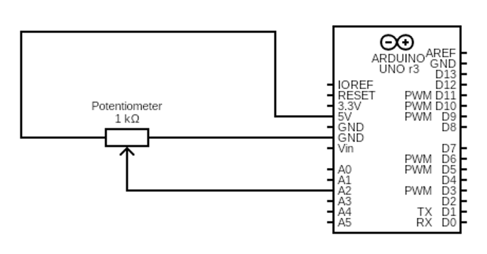
Here the output of the potentiometer is given to the analog pin A2 of the Arduino and the one pin one is connected to the voltage supply that is the five volt pin of Arduino and the other pin is grounded using the ground pin of the Arduino. The significance of the potentiometer is that it can be used where a device needs low voltage as compared to the other devices this will limit the voltage and protect the circuit from frying.

Source code is given below:
int analogpin= A2;
void setup() {
Serial.begin(9600);
}
void loop() {
value=analogRead(A2);
Serial.print("potentiometer output:");
Serial.println(value);
delay(5000);
}

Output
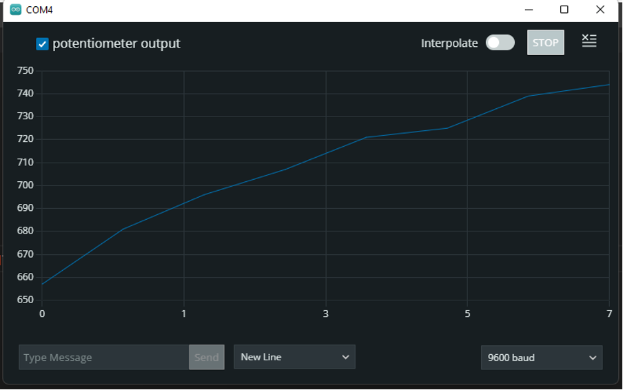
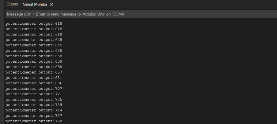
In the output it can be seen that when the knob of the potentiometer is moved towards right the value will increase which means the voltage is increasing and resistance is decreasing. Similarly, the output is displayed by using the serial function and the loop is operating with a delay of 5 seconds.
Conclusion
To interface different sensors with Arduino which have varying output the analog pins are used. Similarly, the varying outputs of the sensors run the circuit to achieve its respective goal as the whole circuit is depending upon the values coming from the sensors. So, in other words the outputs of the sensors will become the inputs for the Arduino board. In this write-up the analog input function serial function is explained briefly with the help of examples.