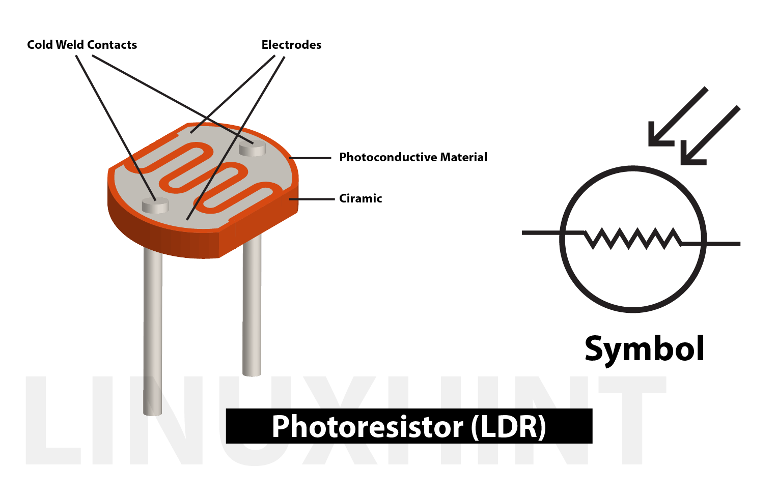
What is a photoresistor?
From the name we can understand that it is also a type of resistor whose resistance values change as the light intensity is changed in its surroundings.
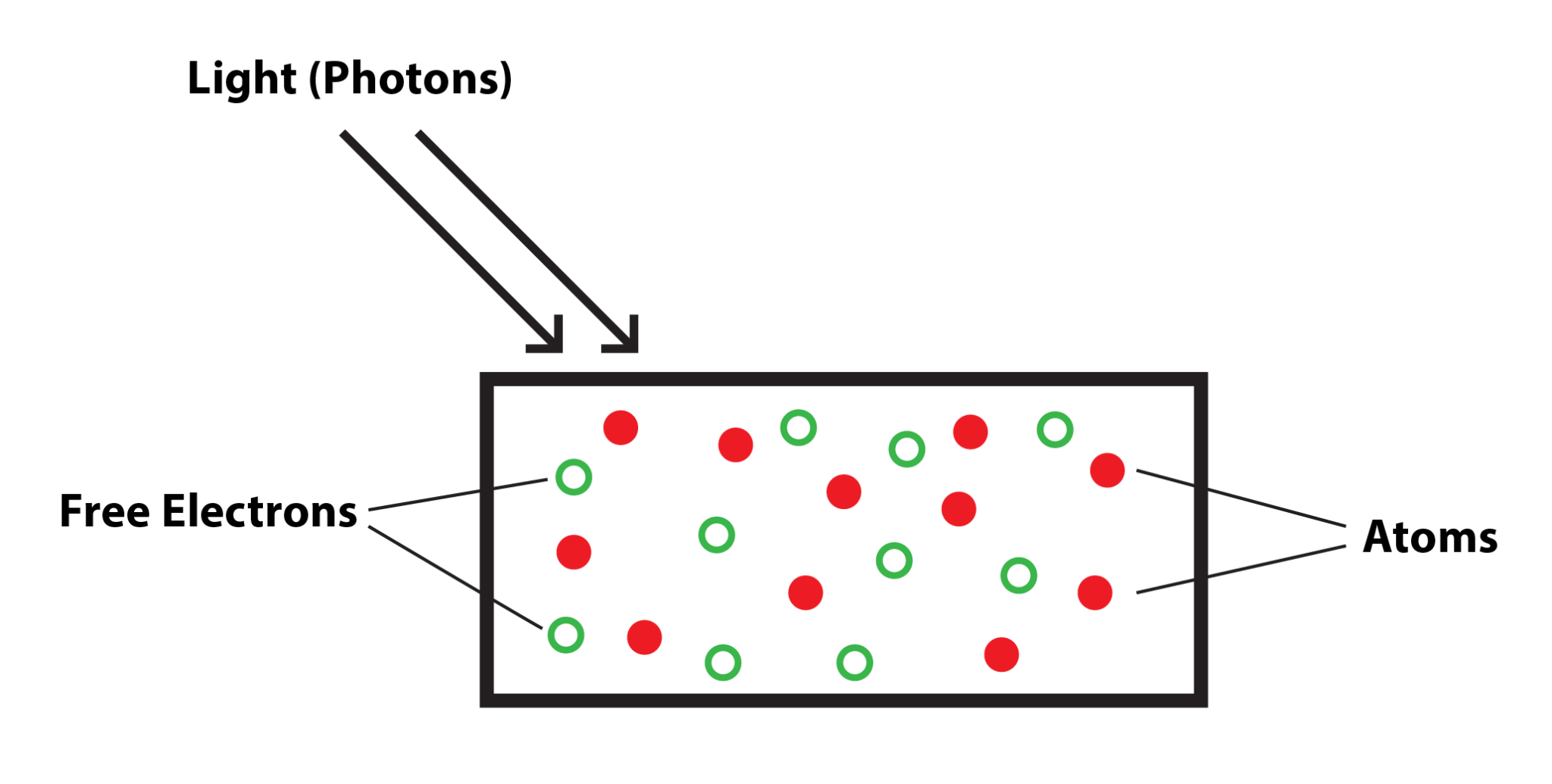
How does a photoresistor work?
The photoresistor is a type of a semiconductor device and when the light intensity increases in its surroundings the electrons in the valence shell break the bonds and become free electrons as a result holes are created which create the flow of electricity. Normally when light intensity is low the resistance of the resistor is quite high and there is no current flow.
However, when the light intensity increases the current starts to flow which causes the resistance to decrease and, in this way, the photoresistor works.
How to control the LED using photoresistor (LDR) with Arduino
To control the lights with a photoresistor is quite simple, we just have to set the threshold value in the microcontroller code by which the LED will turn on and off.The practical application for the use of photoresistor is making automatic street lights which automatically turn off when the sun rises and turn on after sunset.
So, to make the operation of LED based on the light intensity we will be needing the following components:
- Breadboard
- 2 220-Ohm resistors
- Arduino Uno
- Connecting wires
- 1 LED
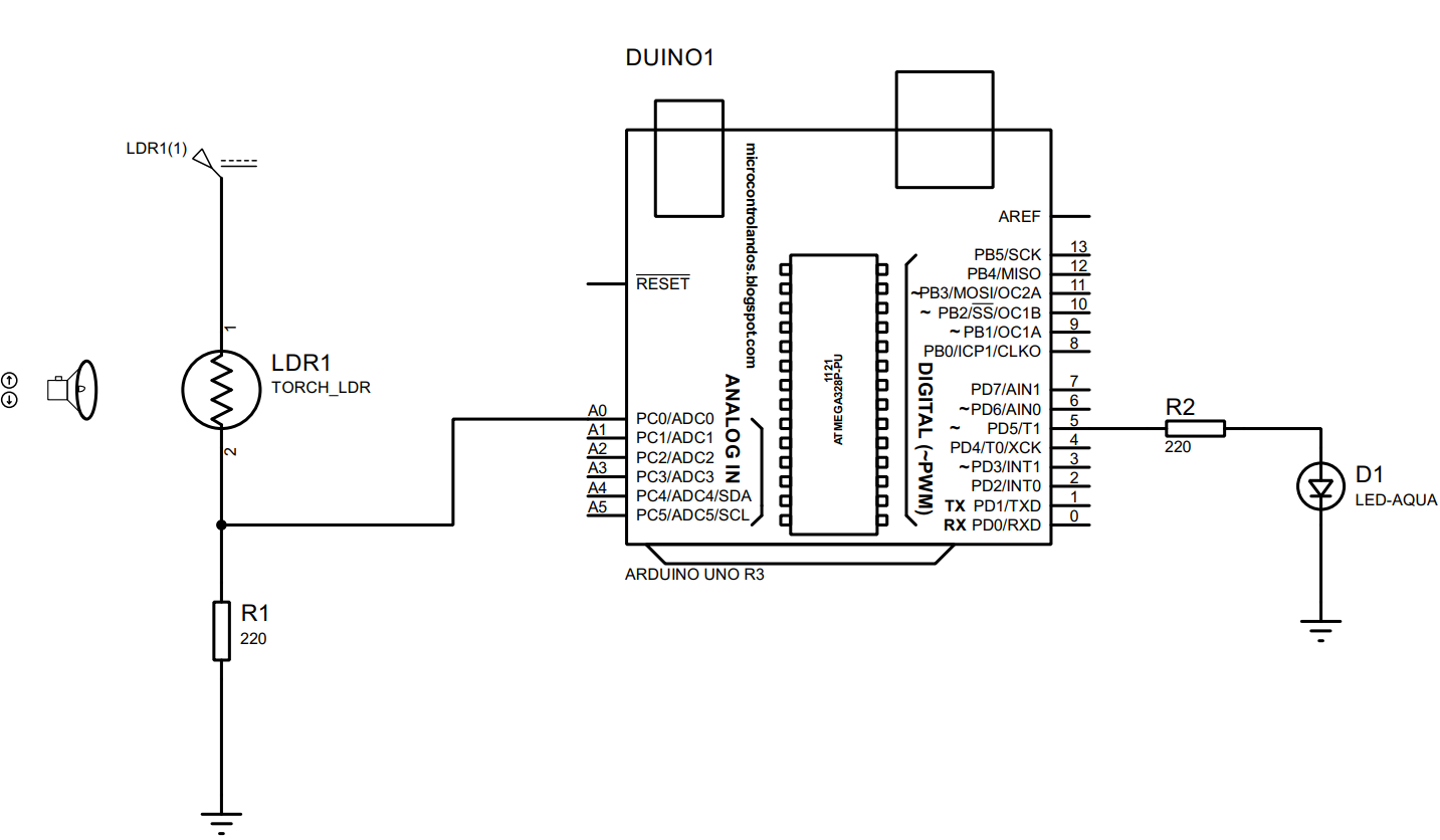
After listing the components, we have designed the circuit that will be controlling the LED using photoresistor and the circuit schematic is given in the image below:
How to create hardware assembly for controlling LED using photoresistor (LDR) with Arduino Uno
To implement the circuit on the hardware we have first defined the hardware assembly given in the image below:
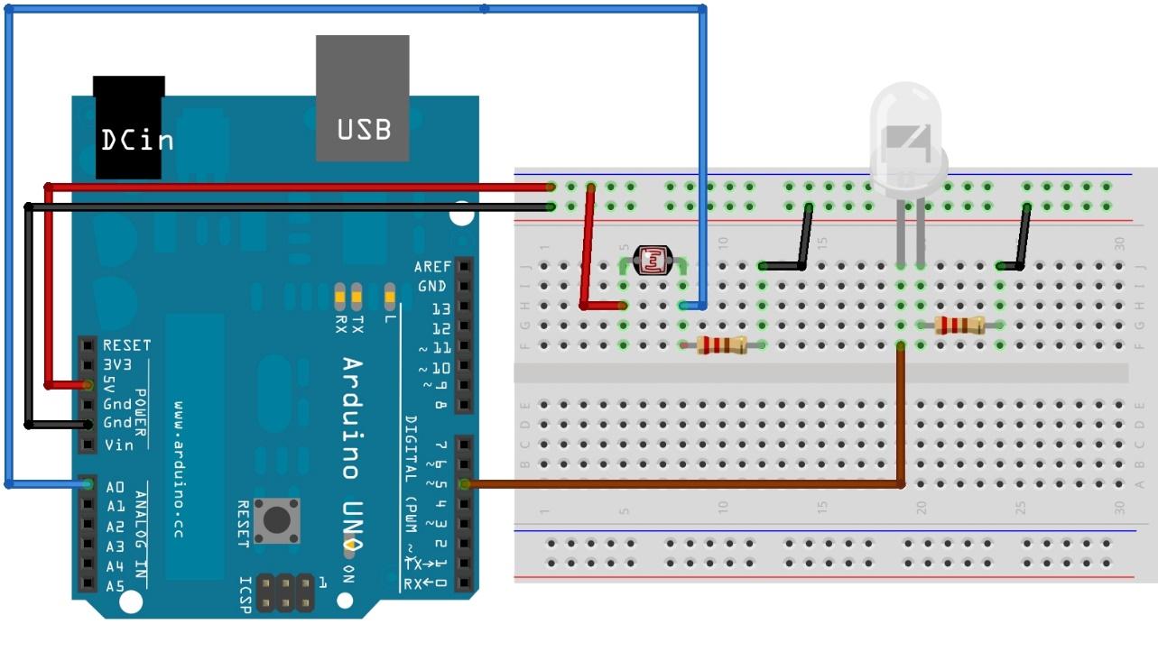
To use the photoresistor for controlling the LED we have connected the photoresistor with the analog pin A0 of the Arduino Uno using the blue wire. Whereas to connect the LED we have used the digital pin 5 of the Arduino Uno using the brown wire.
To connect the photoresistor with the supply we have used the 5-volts and ground pin of the Arduino Uno.
Arduino code for controlling the LED using photoresistor (LDR) with Arduino uno
To control the LED automatically we have to program the microcontroller first using the Arduino IDE and the Arduino code is given below:
int sensor =A0;/* assigning Arduino pin for photoresistor*/
int led= 5;/* assigning Arduino pin for LED*/
void setup() {
Serial.begin(9600); /*setting the baud rate for serial communication*/
pinMode(5, OUTPUT); /* assigning mode to LED pin */
}
void loop() {
// put your main code here, to run repeatedly:
res = analogRead(sensor); /* getting the value of photoresistor*/
Serial.println(res); /* displaying the photoresistor value on serial monitor */
if(res > 100) { /* when the value of sensor is less than 100 */
Serial.println(" Low intensity ");
digitalWrite(5,LOW); /* keep the LED off*/
}
else { /* otherwise turn the light on */
Serial.println("High Intensity ");
digitalWrite(5,HIGH); /* turn the LED on*/
}
delay(1000);
}
To make the function of LED free from Human interface we have defined the threshold of 100 for the photoresistor using the if else conditions. When the value is greater than 100 the LED will turn off otherwise it will remain on.
How to implement the circuit of photoresistor used to control the LED on hardware
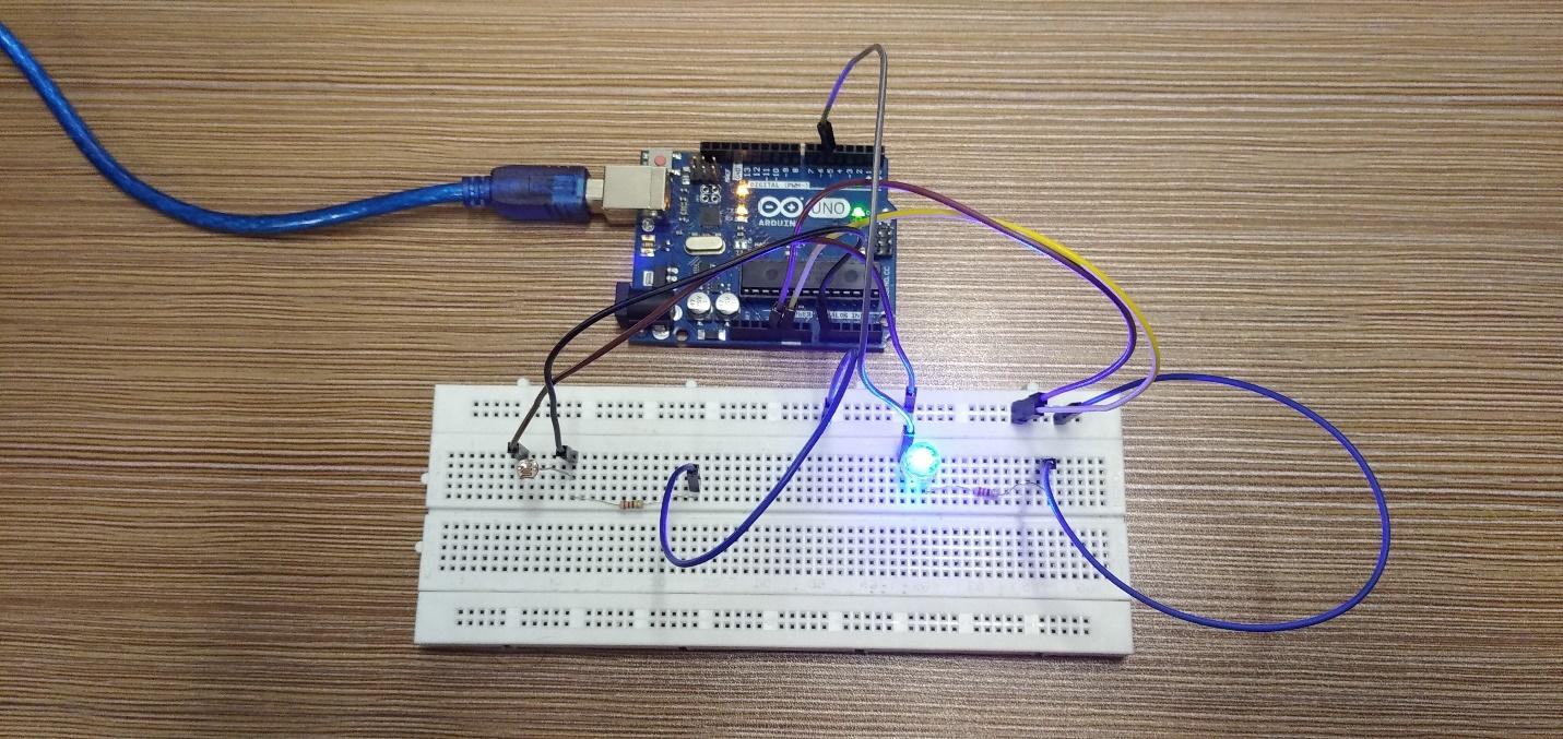
Below is the implementation of hardware assembly described above on the actual hardware and as you can see the LED is on which means the light intensity for photoresistor is quite low:
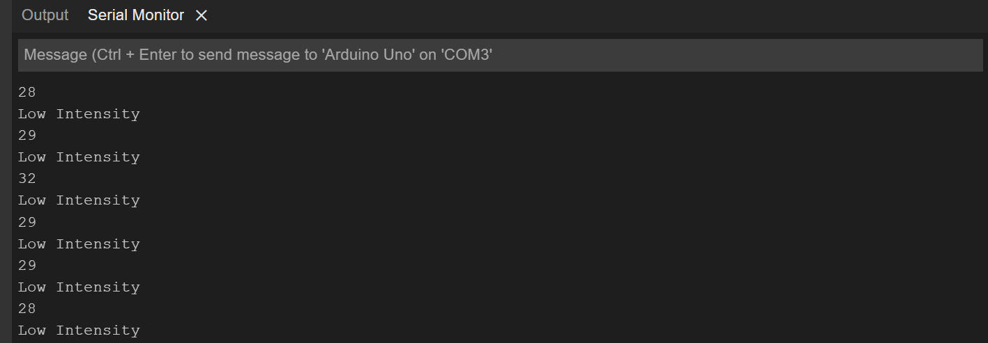
You can also see the values of the photoresistor that the light intensity is quite low in the image given below:
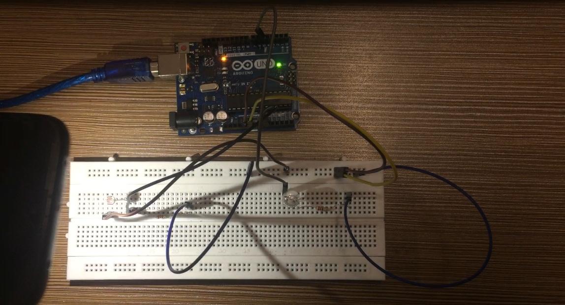
When we increase the intensity of light on the sensor, we can see in the image below that the LED is turned off:
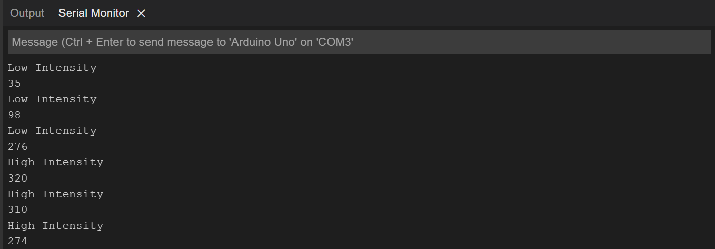
The values of photo resistor are also changed as you can see from the image of the serial monitor given below:
We have posted an animated GIF below that gives a clear idea how a photoresistor works and how we can use it to control the LED:
Conclusion
Photoresistor is a light dependent resistor made up of semiconductor material that can be used in a number of applications like turning on the lights when it’s dark or turning on the water pumps in the morning and many other applications. To make the working of the photoresistor more understandable we have controlled the LED light using the photoresistor and to support how we can achieve it we have given the Arduino code and the hardware with simulation as well.
About the author
Aaliyan Javaid
I am an electrical engineer and a technical blogger. My keen interest in embedded systems has led me to write and share my knowledge about them.