DC Current Measurement with Arduino
There are plenty of reasons why we need to measure DC current using Arduino. We might want to check how much current Arduino and other peripherals are using or to measure battery charging and discharging current.
Most Arduino boards and microcontrollers have ADC built in so first we have to measure DC voltage that can be read by Arduino analog input, later using scale factor during programming we convert that ADC voltage value into current.
To measure DC current using Arduino different sensors and modules are available in the market. One of the most popular and inexpensive sensors available in the market is the ACS712 hall effect sensor.
ACS712 Hall Effect Sensor
Both AC and DC current can be measured using the ACS712 Hall effect sensor. Today we will only focus on measuring DC current. ACS712 operates over 5V, it generates an output voltage at the Vout pin of the sensor which is proportional to the value of current measured by it.
Three different variations of this sensor are available according to current value it measures:
ACS712-5A: 5A sensor can measure current between -5A to 5A. 185mV is the scale factor or sensitivity of the sensor which shows 185mV change in initial voltage represents 1A change in current input.
ACS712-20A: 20A sensor can measure current between -20A to 20A. 100mV is the scale factor or sensitivity of the sensor which shows 100mV change in initial voltage represents 1A change in current input.
ACS712-30A: 30A sensor can measure current between -30A to 30A. 66mV is the scale factor or sensitivity of the sensor which shows 66mV change in initial voltage represents 1A change in current input.
The sensor outputs 2.5V when no current is detected, voltage below this represents negative current while voltage above 2.5V shows positive current.
Scale Factor:
| 5A | 20A | 30A |
|---|---|---|
| 185mV/Amp | 100mV/Amp | 66mV/Amp |
Formula to Measure Current
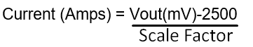
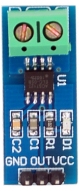
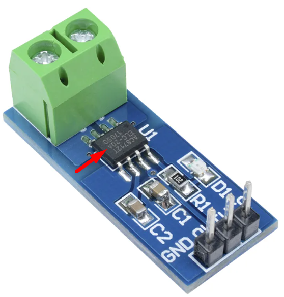
To check for scale factor, look on the ACS712 chip on the hall effect sensor like shown below in the diagram. Here in our case, we will be using the 20A version.
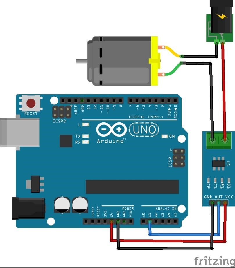
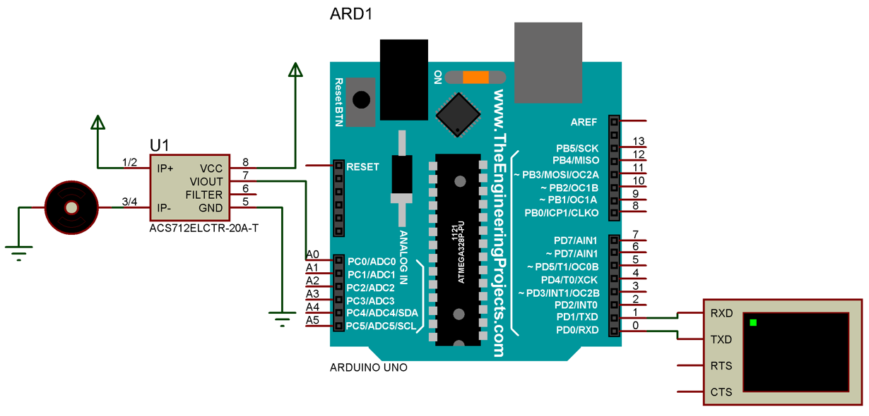
Circuit Diagram
Make sure while connecting Hall effect sensors with load always connect in series as current remains constant in series. Connecting the sensor in parallel can damage the Arduino board or ACS712. Connect sensor in below mentioned configuration:
| Arduino Pin | ACS712 Pin |
|---|---|
| 5V | Vcc |
| GND | GND |
| Analog Pin | Out |
Simulation
Code
double SensorVout = 0;
double MotorCurrent = 0;
/*Constants for Scale Factor in V*/
/*For 5A sensor take scale_factor = 0.185;*/
const double scale_factor = 0.1; /*For 20A sensor*/
/*For 30A sensor take scale_factor = 0.066;*/
/* Variables defined to convert analog data into digital as Arduino has 10 bit ADC SO maximum possible values are 1024*/
/* Reference voltage is 5V */
/* Default voltage value for sensor is half of Reference Voltage that is 2.5V*/
const double RefVolt = 5.00;
const double ADCresolution = 1024;
double ADCvalue = RefVolt/ADCresolution;
double defaultSensorVout = RefVolt/2;
void setup(){
Serial.begin(9600);
}
void loop(){
/* 1000 readings taken to get more precision*/
for(int i = 0; i < 1000; i++) {
SensorVout = (SensorVout + (ADCvalue * analogRead(A0)));
delay(1);
}
// Vout in mv
SensorVout = SensorVout /1000;
/* Using Current formula Convert Vout from sensor into load current*/
MotorCurrent = (SensorVout - defaultSensorVout)/ scale_factor;
Serial.print("SensorVout = "); /*Will print Sensor Vout on serial monitor*/
Serial.print(SensorVout,2);
Serial.print(" Volts");
Serial.print("\t MotorCurrent = "); /*Will print measured DC current*/
Serial.print(MotorCurrent,2);
Serial.println(" Amps");
delay(1000); /*Delay of 1 sec is given*/
}
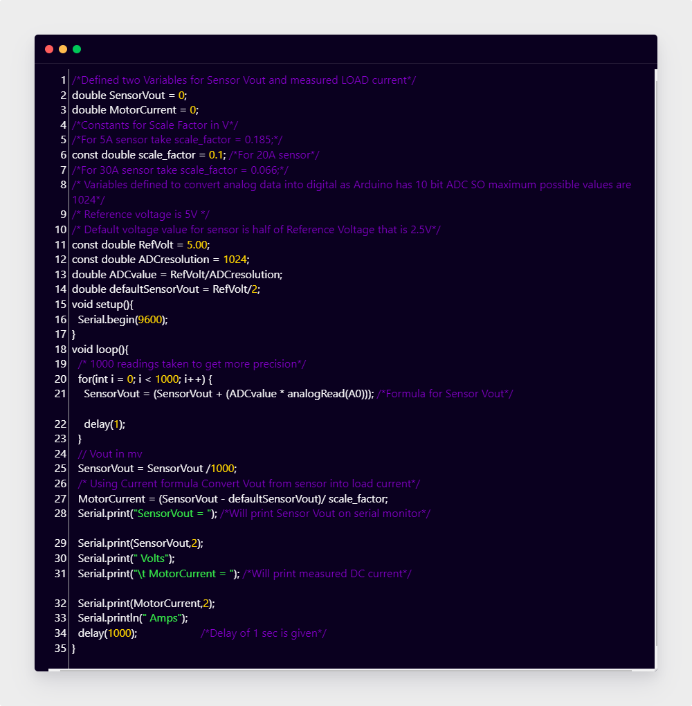
Here in the above code two variables are initialized SensorVout and MotorCurrent, both these variables will store values as voltage and current respectively. Next scale factor is set to 0.1 V (100mV) according to the 20A-ACS712 sensor. Reference voltage is set to 5V and to convert analog input to digital ADC resolution is initialized to 1024. As Arduino has 10-bit ADC which means the maximum it can store is 1024 values.
As explained above scale factor will take reading according to total deviated voltages from 2.5V. So, 0.1V change in Vout of sensor will be equal to 1A of input current.
Next in the loop section a for loop is initialized to take 1000 readings to get a more precise value of output current. Sensor Vout is divided by 1000 to convert values into mV. Using the motor current formula, we have determined our load current. Last section of code will print both sensor Vout voltages and measured current.
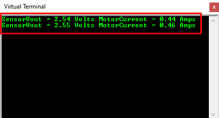
Output
Here in output Sensor vout is less than 2.5V so output measured motor current is negative. Output current is negative due to DC motor reverse polarity.
Conclusion
Measuring DC current using Arduino required some external sensor or module. One of the widely used hall effect sensors is ACS712, which not only has a great range of current measuring for DC as well as AC current. Using this sensor, we have measured the DC current of a running DC motor and the output result is shown in the terminal window.