Light Dependent Resistor has a vast application in light dependent projects. With the help of a microcontroller like the Arduino Nano, the LDR can be used to control various devices based on the light intensity level. This guide covers basics of LDR and its applications with the Arduino Nano.
This article contents includes:
2: Applications of LDR with Arduino Nano
3: Interfacing LDR with Arduino Nano
1: Introduction to LDR Sensor
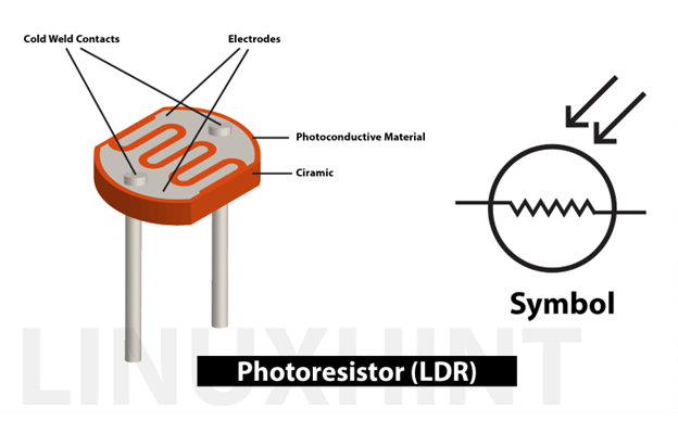
A Light Dependent Resistor (LDR) is a type of resistor that changes its resistance based on the intensity of light it is exposed to. In darkness, its resistance is very high, while in bright light its resistance is very low. This change in resistance makes it best for light sensing projects.
LDR gives analog voltage output which will be read by Arduino ADC at analog pins. The analog input pin on the Arduino uses an ADC to convert the analog voltage from the LDR into a digital value. The ADC has a range of 0 to 1023, with 0 representing 0V and 1023 representing the maximum input voltage (usually 5V for the Arduino).
Arduino will read the analog values using the analogRead() function in your code. The analogRead() function takes the analog input pin number as an argument and returns the digital value.
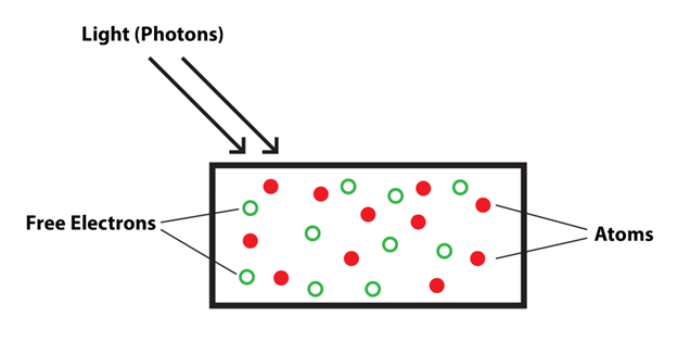
Photons or light particles play a crucial role in the operation of LDRs. When light falls on the surface of an LDR, photons are absorbed by the material, which then frees electrons in the material. The number of free electrons is directly proportional to the intensity of light, and the more electrons that are freed, the lower the resistance of the LDR becomes.
2: Applications of LDR with Arduino Nano
Following is the list of some common applications of LDR with Arduino:
-
- Automatic lighting control
- Light activated switch
- Light level indicator
- Night mode in devices
- Light-based security systems
3: Interfacing LDR with Arduino Nano
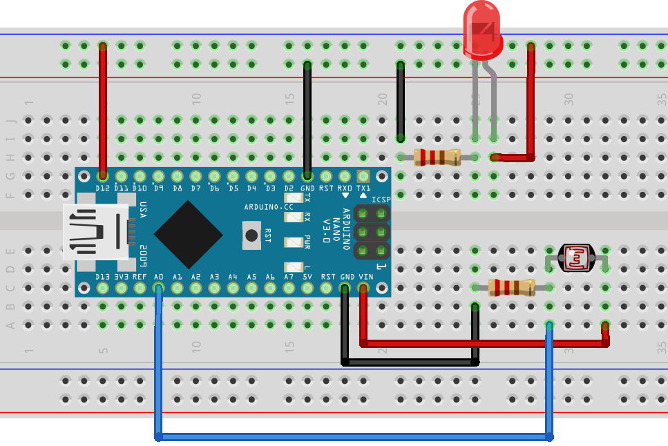
To use an LDR with the Arduino Nano, a simple circuit needs to be created. The circuit consists of the LDR, a resistor, and the Arduino Nano. The LDR and the resistor are connected in series, with the LDR connected to the analog input pin of the Arduino Nano. A LED will be added to the circuit that can test LDR working.
3.1: Schematic
Following image is the schematic of Arduino Nano with LDR sensor.
3.2: Code
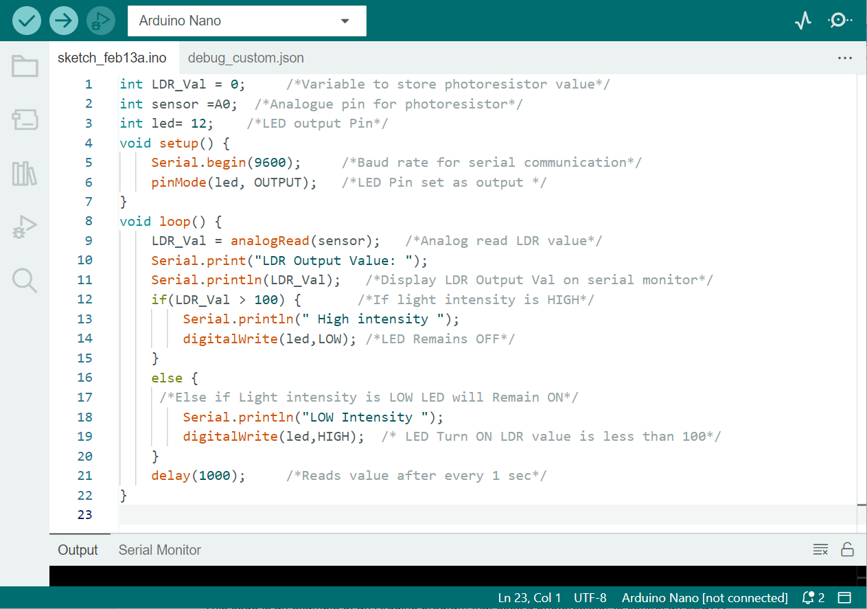
Once the circuit has been set up, the next step is to write the code for the Arduino Nano. The code will read the analog input from the LDR and use it to control an LED or other device based on different light levels.
int sensor =A0; /*Analogue pin for photoresistor*/
int led= 12; /*LED output Pin*/
void setup() {
Serial.begin(9600); /*Baud rate for serial communication*/
pinMode(led, OUTPUT); /*LED Pin set as output */
}
void loop() {
LDR_Val = analogRead(sensor); /*Analog read LDR value*/
Serial.print("LDR Output Value: ");
Serial.println(LDR_Val); /*Display LDR Output Val on serial monitor*/
if(LDR_Val > 100) { /*If light intensity is HIGH*/
Serial.println(" High intensity ");
digitalWrite(led,LOW); /*LED Remains OFF*/
}
else {
/*Else if Light intensity is LOW LED will Remain ON*/
Serial.println("LOW Intensity ");
digitalWrite(led,HIGH); /* LED Turn ON LDR value is less than 100*/
}
delay(1000); /*Reads value after every 1 sec*/
}
In above code we use an LDR with Arduino Nano that will control LED using the analog input coming from LDR.
The first three lines of code declare variables to store the photoresistor value, the analog pin for the photoresistor, and the LED output pin.
In the setup() function, the serial communication is initiated with a baud rate of 9600 and LED pin D12 is set as output.
In the loop() function, the photoresistor value is read using the analogRead() function, which is stored in the LDR_Val variable. The photoresistor value is then displayed on the serial monitor using the Serial.println() function.
An if-else statement is used to control the LED based on the light intensity detected by the photoresistor. If the photoresistor value is greater than 100, it means the light intensity is HIGH, and the LED remains OFF. However, if the photoresistor value is less than or equal to 100, it means the light intensity is LOW, and the LED turns ON.
Finally, the program waits for 1 second using the delay() function before reading the photoresistor value again. This cycle repeats indefinitely, making the LED turn ON and OFF based on the light intensity detected by the photoresistor.
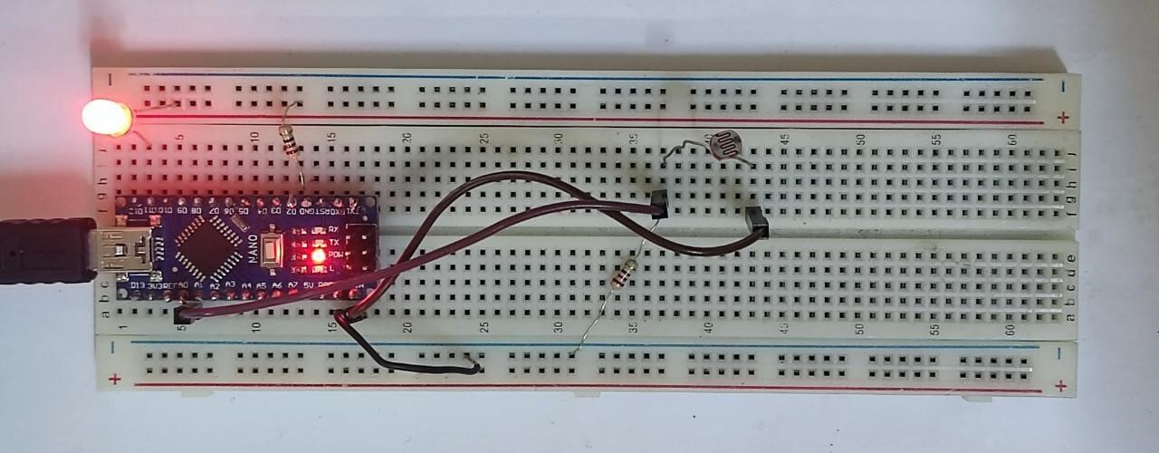
3.3: Output under Dim Light
Light intensity is less than 100 so LED will remain ON.
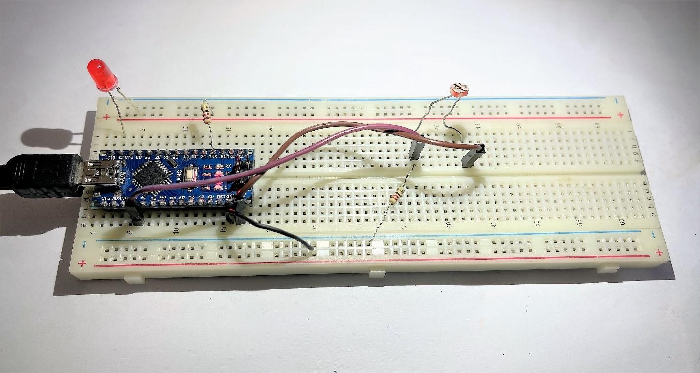
3.4: Output under Bright Light
As light intensity increases the LDR value will increase and LDR resistance will decrease so LED will turn OFF.
Conclusion
The LDR can be interfaced with Arduino Nano using an analog pin. The LDR output can control light sensing in various applications. Whether it’s used for automatic lighting control, light-based security systems, or just a light level indicator, the LDR and Arduino Nano can be interfaced to create projects that respond to changes in light intensity.