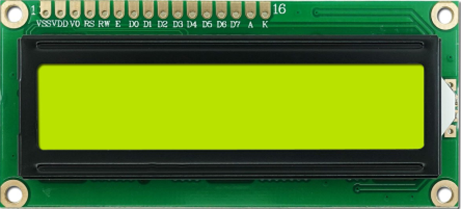
16×2 LCD display for Arduino
This display is the most commonly used display for the Arduino projects as it can display character, numbers and some custom-made characters. Moreover, it has 16 columns and 2 rows for displaying the data and has an option of both 4-bit and 8-bit communication.
| Pin | Description |
|---|---|
| 1 (GND) | For grounding the display this pin is used |
| 2 (VCC) | For powering the display with 5 volts |
| 3 (V0) | For contrast adjustment |
| 4 (RS) | For selecting the register (command / data) |
| 5 (RW) | For reading and writing |
| 6 (E) | Enable pin for the display |
| 7 (D0) | data pins for input and output |
| 8(D1) | |
| 9(D2) | |
| 10(D3) | |
| 11(D4) | |
| 12(D5) | |
| 13(D6) | |
| 14(D7) | |
| 15(A) | Anode of backlight of display |
| 16(K) | Cathode of backlight of display |
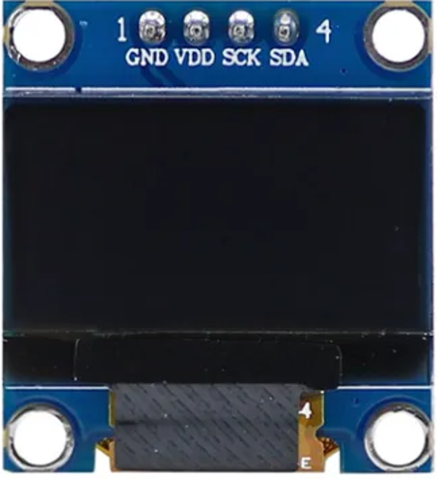
128×64 OLED Graphic Display for Arduino
This display module uses the organic light emitting diode which improves its image quality. Similarly, this display module consumes less power, is more reliable and gives the full viewing angle of the picture. This display works on voltage from 3.3 to 5 volts and has four pins.
| Pins | Description |
|---|---|
| 1 | This pin used for grounding the display |
| 2 | This is used for giving voltage supply to the display |
| 3 | This pin will give the clock signal for both types of communication either SPI or I2C |
| 4 | The fourth pin is the data pin through which it will receive data from Arduino |
128×64 Graphical LCD display for Arduino
This display comes with different models of LCD drivers and its pin configuration depends on the model of LCD driver. This display is much bigger in size as compared to other displays as it has 128 columns and 64 rows for displaying the data. Similarly, this module can be used to display the characters of different sizes by using different pixel combinations and also it supports the feature of displaying the animations and images. The operating voltage for this display is 5 volts and the interfacing of this module is similar to the 16×2 liquid crystal display.
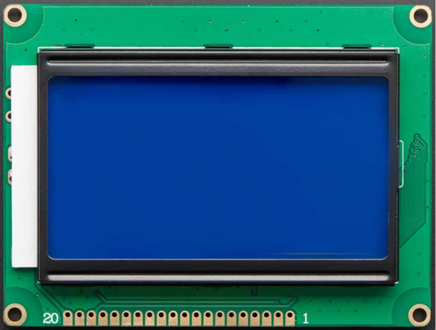
Here we have used the display having the graphic display having a driver model of KS0108 which has 20 pins in total.
| Pin | Description |
|---|---|
| 1 (VDD) | For supplying the voltage to the module (5V) |
| 2 (VSS) | For grounding the display this pin is used |
| 3 (V0) | To control the contrast of the display |
| 4 (RS) | Command and data register pin |
| 5 (RW) | Reading and writing selection for the data |
| 6 (E) | For enabling the display this pin is used |
| 7 | Data pins for input and output |
| 8 | |
| 9 | |
| 10 | |
| 11 | |
| 12 | |
| 13 | |
| 14 | |
| 15 (CSI) | For enabling only, the left half of the display |
| 16 (CS2) | For enabling the right half of the display |
| 17 (RST) | To reset the display module |
| 18 (VEE) | Negative output voltage |
| 19 (LED+) | Positive terminal for Power for the backlight |
| 20 (LED-) | Negative terminal for Power for the backlight |
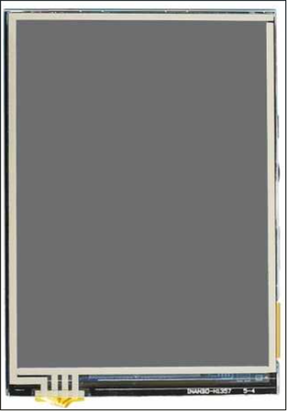
MAR3501 3.5 INCH TFT Display for Arduino
This display is the best suitable option for the projects in which the graphical user interface is required. This display comes with the color display of 65K and has a resolution of 320×480. Similarly, this display uses 8-bit data transmission for quick transmission and operates on the voltage ranging from 3.3 to 5 volts.
| Pin | Description |
|---|---|
| 1 (5v) | For powering the display with 5 volts |
| 2 (3V3) | For powering the display with 3.3 volts |
| 3 (GND) | For grounding the display this pin is used |
| 4 (LCD_D0) | 8-bit data pins for input and output |
| 5(LCD_D0) | |
| 6(LCD_D0) | |
| 7(LCD_D0) | |
| 8(LCD_D0) | |
| 9(LCD_D0) | |
| 10(LCD_D0) | |
| 11(LCD_D0) | |
| 12(LCD_RST) | To reset the display this pin is used |
| 13(LCD_CS) | To select the display area |
| 14(LCD_RS) | For selecting the read and write register |
| 15(LCD_WR) | Pin for Display write control |
| 16 (LCD_RD) | Pin for display read control |
| 17(SD_SS) | For section of the SD card |
| 18(SD_DI) | Input for SD card |
| 19(SD_D0) | Output for SD card |
| 20(SD_SCK) | Clock for the SD card |
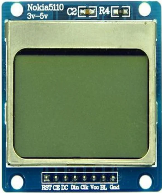
Nokia 5110 Liquid crystal display for Arduino
This display has 84×48 pixels having total 8 pins and operates only on 3.3 volts. This type of display is used where a basic level of graphical user interface is required as from the name it is clear that this display was used for Nokia 5110 cell phone. Similarly, this display is a better option as compared to the 16×2 liquid display as it has better graphics and can display a large number of custom characters.
| Pin | Description |
|---|---|
| 1(RST) | Pin for resetting the display |
| 2(CE) | For enabling the display |
| 3(DC) | Data command |
| 4(DIN) | Data input |
| 5(CLK) | Clock Input |
| 6(VCC) | Voltage supply (3.3V) |
| 7(BL) | Supply for Backlight |
| 8(GND) | For Grounding the display |
Conclusion
For displaying the inputs and outputs of the Arduino program different types of displays can be interfaced with Arduino boards. The type of display depends on its compatibility with Arduino board and type of the data that is to be displayed on the module. In this write-up five best compatible display modules are given with their pin configuration and technical specifications.