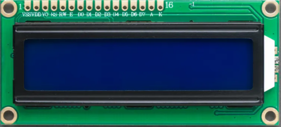
16×2 liquid crystal display (LCD)
The 16×2 liquid crystal display can be used in embedded systems where displaying a limited amount of data is necessary. This display comes with two lines of data and each line is divided into sixteen columns. Each row has a block of 8 rows and 5 columns also called cells or in other words we can say that each cell of the row has 40 pixels.
The LCD has a capacity of displaying 32 characters in two rows and these characters can be integers, alphabets or symbols. Similarly, the LCD can also display some user made characters as well by turning some dots of the cell on and off. In short there is a wide variety of characters that can be shown on the LCD.
Pin configuration for 16×2 LCD
There is a total of 16 pins of the 16×2 display module and explanation of each pin is mentioned below:
VSS pin : This pin is used for grounding the liquid crystal display.
VDD pin : To connect the LCD to the supply the VDD pin is used, and it is maximum 5 volts.
V0 pin : To adjust the brightness of the display module the V0 pin is used. Usually this is connected with the output of the potentiometer. Similarly, by varying the resistance of the potentiometer we can adjust the brightness of the LCD.
RS pin : To select between the command and the data register the RS pin is used. The command register is used to store the command given to LCD like function for clearing the LCD, function for setting the position of the cursor and many more.
Similarly, to display the data on the LCD screen the data register is used which stores this data. So, when the data is to be displayed the value for the RS pin becomes 1 and when the command is to be sent the value for the pin becomes 0.
RW pin : This pin is used for reading and writing the data into the register which is then displayed on the LCD. When there is no data for writing the register the pin will be in reading mode that is its state will be 0. Similarly, when there is data to be written then the state of the pin will be 1. Normally this pin is grounded because mostly the read register is used for only displaying the data.
E pin : This pin is also called the enable pin of the module as it sends the signal to the LCD. This pin sends the data to the data pins of the LCD when the data is to be sent on the LCD. This pin has a high state that is 1.
Data pins : The 16×2 LCD has a number of 8 pins for receiving and sending the data and mostly the only four data pins are used as it requires less pins of the device that is to be interfaced. The liquid crystal module works in two modes one is the 8-bit and the other is the 4-bit mode.
In the 8-bit mode all the 8 data pins are used and the data of 8 bits can be transferred simultaneously. However, in 4- bit mode the 8-bit data is divided into two parts that are 4-bit for each part, but this mode requires less number of pins.
A and K pins : The A pin can also be called as anode pin for the LCD as it is used to supply power to the backlight of LCD module and the K pin is cathode pin for the LCD as it is connected to the ground terminal.
To summarize the pin configuration we have given a table for the the pins of the 16×2 LCD
| Pin | Name | Description |
| 1 | VSS | Pin used for grounding the LCD |
| 2 | VDD | Pin used for connecting voltage supply with LCD |
| 3 | V0 | Pin used for controlling the brightness of the display module |
| 4 | RS | Pins for selection of data and command register |
| 5 | RW | Pin for using the write register of LCD |
| 6 | E | Pin used for sending the data to the data pins of LCD |
| 7-14 | D0-D7 | Data pins of the LCD |
| 15 | A/LED+ | Anode for the backlight of LCD |
| 16 | K/LED- | Cathode for the backlight of LCD |
The pin configuration can be further understood by the image of the LCD posted below
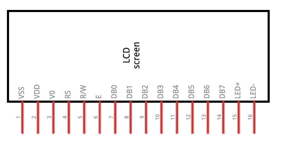
In the above image LED+ and LED- are A and K pins respectively.
Conclusion
The liquid crystal display (LCD) is a viable option for displaying the parameters used in an Arduino program or a project. The liquid crystal display comes in multiple sizes but mostly the 16×2 size is preferred as it is easy to use and easy to interface it with Arduino. In this write-up the 16×2 LCD is explained briefly which will make it easy for the reader to interface it with any device.