Interfacing the 7 segments with Arduino Uno
From the name we can say that this display is further divided into the seven segments used to display the numeric data of the Arduino code. This display is small in size and we can also combine two or more displays if big numeric data is to be displayed. Such a display is feasible in the projects like building a countdown timer, displaying the temperature, number of visitors or displaying the token numbers in the bank or in the hospitals.
We have given the image of the seven-segment display below from which you can have a clearer idea of what a seven-segment display is and also, we have given the schematic of the seven-segment display.
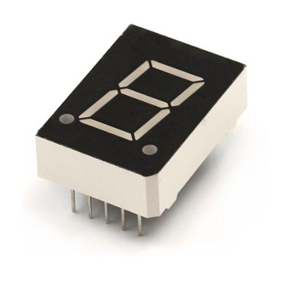
This segment comes in two configurations either common cathode or common anode and There are a total 10 pins of the module seven of which are for each segment of the display. Whereas the two pins are either anode or cathode and we can use any one of them. There is one pin for the dot present on the bottom right of the display which comes handy when the value having decimal is to be displayed.
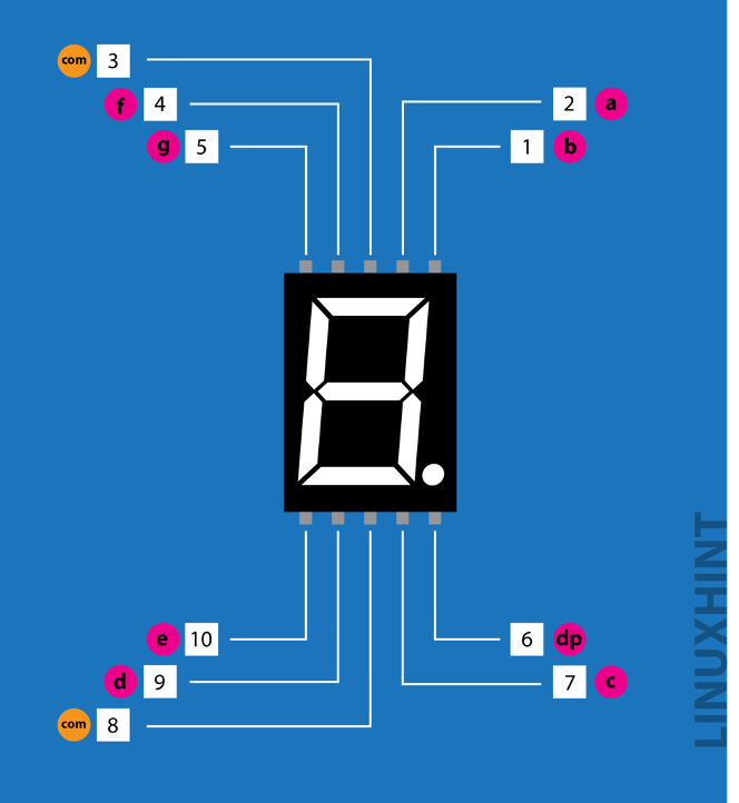
The pins of the display are taken in the alphabetic order starting from a to g and we have provided the image below that shows the pin configuration of the display:
| Pin No. | Name (starting from top right corner) | Description |
|---|---|---|
| 1 | b | Pin for controlling the top right LED |
| 2 | a | Pin for controlling the topmost LED |
| 3 | Vcc or GND | Pin to connect the display either to ground or voltage depending upon the display configuration |
| 4 | f | Pin for controlling the top left LED |
| 5 | g | Pin for controlling the middle LED |
| 6 | dp | Pin for controlling the dot LED on the bottom right |
| 7 | c | Pin for controlling the bottom right LED |
| 8 | Vcc or GND | Pin to connect the display either to ground or voltage depending upon the display configuration |
| 9 | d | Pin for controlling the bottom LED |
| 10 | e | Pin for controlling the bottom left LED |
For interfacing the seven-segment display with Arduino we have created a circuit whose schematic is given below:
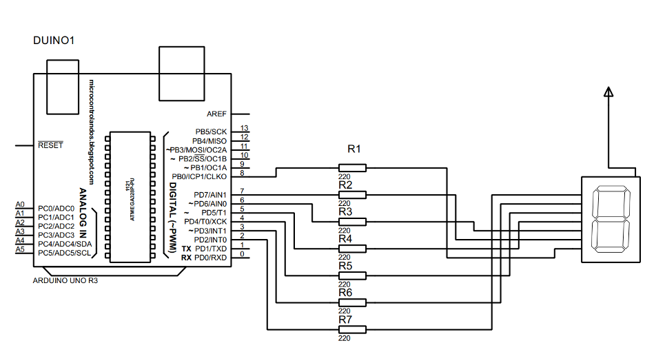
In the schematic we have used the seven-segment having a common anode you can use the other configuration as well.
Hardware assembly for interfacing seven-segment with Arduino Uno
To assemble the hardware for connecting the seven-segment with Arduino we have used the following components
- Arduino Uno
- Connecting wires
- Breadboard
- Seven-segment display (either with common anode or cathode)
- Seven 220-ohm resistors
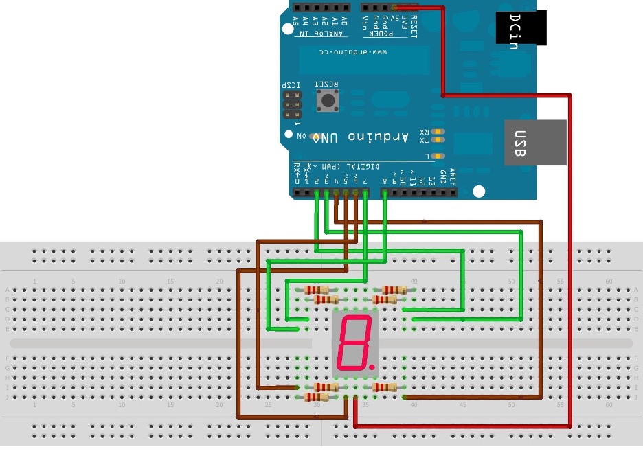
We have provided the image below for the hardware assembly of interfacing the seven-segment with Arduino to give a little bit more detail of the connections:
We have connected the seven segment display with Arduino starting from a and going to g. For distinguishing the upper and lower connections we have used different colors for the pins on the top and below. The green color wires connect the upper pins of the seven segment while the lower pins are connected to the Arduino using the brown pins.
How to install the library for seven-segment display in Arduino IDE
To understand how we can install the library of the seven-segment we have provided the image below which shows the step wise process of installation of seven-segment library:

- To install the library, we have to open the library manager of the Arduino IDE by clicking on the box highlighted in the figure above having one written on it.
- After you have opened the library manager type seven-segment in the search bar of the library manager and then you will come across a long list of libraries for seven-segments.
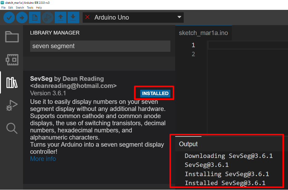
- From the list first you have to find the SevSeg library by the Dean Reading.
- After finding that specific library you have to click on the install icon highlighted in red having 4 written on it and this icon will appear as you move the cursor downward.
As soon as you click on the install the library will start to install and you will see an icon of installed will appear in front of the name of the library and the installation status will also appear in the output menu of the IDE. It can be seen in the image we posted below:
Arduino code for interfacing the seven-segment with Arduino Uno using SevSeg library
The seven-segment can be interfaced with Arduino Uno by two ways : one by using the specific library for the seven segment and the second is by giving binaries for each digit we want to display on the seven segment
Below we have given the code that how we can interface the seven-segment using its library
SevSeg sevseg;// initializing the variable for seven-segment
void setup()
{
byte sevenSegments = 1;/*defining the number of seven- segments here we are using only one seven-segment */
byte CommonPins[] = {};/* defining the common pins for the seven-segment*/
byte LEDsegmentPins[] = {2, 3, 4, 5, 6, 7, 8 };/* assigning the Arduino pins for each segment from a to g */
bool resistorsOnSegments = true; /*assigning Boolean type to the registers of the seven=segment*/
sevseg.begin(COMMON_ANODE, sevenSegments, CommonPins, LEDsegmentPins, resistorsOnSegments);/* initializing the configuration of the seven-segment */
sevseg.setBrightness(80);// giving the brightness to the seven-segment
}
void loop()
{
for(int i = 0; i < 10; i++)/* generating numbers from 0 to 9 using for loop*/
{
sevseg.setNumber(i); /*displaying the for loop values on seven-segment*/
sevseg.refreshDisplay(); /* refreshing the seven-segment display after every iteration */
delay(1000); /* time after which the for loop will iterate again*/
}
}
Using the library for seven segments we have run the Arduino code first by defining the library of the seven segment and defining the respective variable used for using functions of the seven-segment.
Next we have defined the number of the segments that we are using and then used the sevseg.begin() function for defining the configuration of the seven-segment display. Here in the code we have used the common Anode configuration of the seven-segment.
For demonstration purposes we have generated the numbers from 0 to 9 using the for loop in the loop section of the Arduino code and to display the numbers on the seven-segment we have used the sevseg.setNumber() function.
Arduino code for interfacing seven-segment without library
To give the idea how we can interface the seven-segment without using any library we have the respective code below:
byte segCode[10][7] = { /*declaring an array of the number from 0 to 9 in the order from a of g*/
//a b c d e f g
{ 0, 0, 0, 0, 0, 0, 1}, // for displaying 0
{ 1, 0, 0, 1, 1, 1, 1}, // for displaying 1
{ 0, 0, 1, 0, 0, 1, 0}, // for displaying 2
{ 0, 0, 0, 0, 1, 1, 0}, // for displaying 3
{ 1, 0, 0, 1, 1, 0, 0}, // for displaying 4
{ 0, 1, 0, 0, 1, 0, 0,}, // for displaying 5
{ 0, 1, 0, 0, 0, 0, 0}, // for displaying 6
{ 0, 0, 0, 1, 1, 1, 1}, // for displaying 7
{ 0, 0, 0, 0, 0, 0, 0}, // for displaying 8
{ 0, 0, 0, 0, 1, 0, 0}, // for displaying 9
};
void displayDigit(int digit) /*creating a function for initializing the each segment of the display*/
{
for (int a=0; a < 7; a++)
{
digitalWrite(segPins[a], segCode[digit][a]);/* instructing the respective segments for the numbers from 0 to 9 */
}
}
void setup()
{
for (int a=0; a < 7; a++) // assigning the OUTPUT mode to all the 7 seven-segments*/
{
pinMode(segPins[a], OUTPUT);
}
}
void loop()
{
for (int b = 0; b < 10; b++)/* generating numbers from 0 to 9 */
{
displayDigit(b);/*displaying the numbers generated*/
delay(1000);
}
}
In the above code we have used the seven-segment having common anode but if you want to interface the seven-segment having common cathode we can just invert the binaries.
To summarize the code we have compiled, we can say that first we have defined the binaries for each number and then we have created the display function that will return the digit on the seven-segment by using the binaries declared above.
Next in the setup section of the code we have assigned all the seven-segments to work in the output mode. After that in the loop section we have used the for loop for generating the numbers and then using the displayDigit() function declared above we have displayed the numbers on the seven-segments.
Hardware implementation of interfacing the seven-segments with Arduino Uno
To give the better idea of interfacing the seven-segment with Arduino we have implemented the hardware assembly described above and provided the figure for the hardware implementation which is given below:

To demonstrate the working of the Arduino code compiled for interfacing the seven-segment with Arduino is given below:
Conclusion
To display the parameters of the Arduino program we have to interface any display with the Arduino board. In the market there are a wide variety of displays available that can be interfaced with Arduino, but it depends on the type and amount of data that is to be displayed. For a limited amount of data and only for displaying the numbers we can use the seven-segment display as they are easy to work with. So we have interfaced the seven-segment display with Arduino Uno in this guide.