To interface multiple devices with microcontrollers, the Arduino boards are the viable option as they make the interfacing of the device easy. Devices like relays can be interfaced with Arduino that help in controlling multiple devices attached with the microcontroller board. We have interfaced a 2-relay module with Arduino Uno and explained the functionality of the relay in detail.
What is a relay
The purpose of the relay is the switching of the devices that work at higher voltage level or when needed both AC and DC devices in the same circuit. In other words, we can say that a relay is a switch that is controlled electrically which is used to turn on and off the devices attached to it.
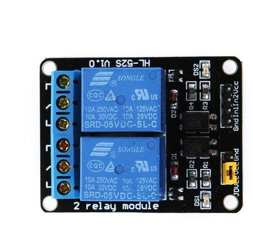
Each relay has a total of 5 pins: two pins are for grounding or supplying voltage and two pins for the signal input one for each relay. Furthermore, the other three pins are common pin, normally open and normally close pins and to operate the relay always remember to short the (JD-VCC) pin and the (VCC) pin of the relay. To give a clear understanding of the pins of the module we have posted a table below for the pin configuration followed by the image of the 2-relay module.
| Pin | Description |
|---|---|
| Commonly used pins for both relays | |
| 1-(Vcc) | To supply 5 volts to the relay module |
| 2-(GND) | To connect the module with ground |
| 3-(In1) | To give Signal to the first relay |
| 4-(In2) | To give signal to the second relay |
| Separate Pins for each relay | |
| 1-(COM) | Pin used to supply the voltage to the relay for controlling the device |
| 2- (NO) | This is pin whose contacts are open normally |
| 3- (NC) | This pin has closed contacts normally |
COM pin of relay (Common Pin)
This is the center pin of the relay and the main voltage that has to be given to the connected device is connected to this pin.
NC pin of the relay (Normally Closed)
The next pin to the common pin is the normally closed pin of the relay whose contacts are closed in the normal conditions. In other words, we can say that the common pin and the normally closed pin are connected with each other
NO Pin of the relay (Normally Open)
This pin is the first pin of the relay, and its contacts are normally open which means that there is no supply voltage at that pin. The device which is to be controlled is connected to that pin and when the signal for turning on the device is given to the relay it closes the contacts and the device turns on.
One thing to always remember while using the relay module
While using the relay module do not forget to either short the JD-VCC pin to the other VCC pin of the module or connect it with a separate supply because the relays need an optical isolator that prevents any noise interference to the signal of the relay. Similarly, if you are not using the relay module instead you are using a simple relay you need to connect the flyback diode with the relay. As stated above to isolate the relay we can use a separate supply of the relay module to prevent the interference in the signal.
Interfacing relay with Arduino Uno
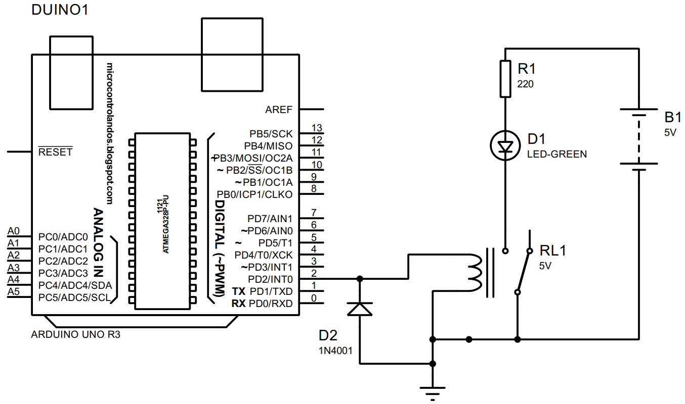
To interface a relay with Arduino and to demonstrate the working of the relay we have posted the schematic of the circuit having a single relay connected with Arduino followed by the list of components required to interface the relay with Arduino
- Arduino Uno
- Relay module
- Connecting wires
- Breadboard
- LED
- 1 220-ohm resistor
Hardware assembly for interfacing relay with Arduino Uno
In the hardware we have used a two-relay module, but we are using the single relay from that relay module. You can use a single relay module as well. To give you a clear picture of connections for interfacing the relay with Arduino we have posted an image of the hardware assembly of interfacing the relay module with Arduino:
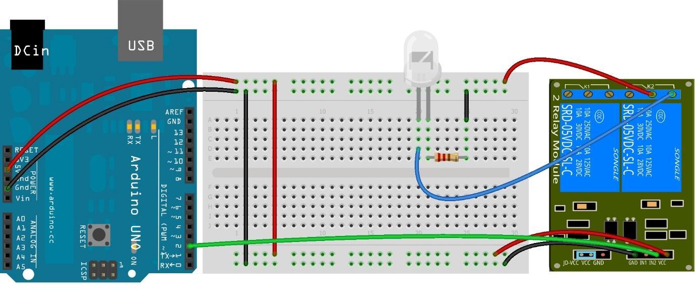
We have connected the relay with Arduino in such a way that first we have connected the common pin that is the red wire of the second relay module with the 5-volt supply from the breadboard. Next, we have connected the normally open blue wire pin of the second relay module with the LED placed on the breadboard. To give the signal for turning the LED on and off the green wire connects the signal pin of the relay with the Arduino at its pin 2.
Arduino code for interfacing relay with Arduino to control the LED
To interface the relay with Arduino the Arduino code we complied is given below:
pinMode(relaypin,OUTPUT);/* assigning the relay pin as an output of Arduino*/
digitalWrite(relaypin,LOW);/* giving the relay pin state of LOW initially */
}
void loop() {
digitalWrite(relaypin,HIGH);/* assigning the relay pin if state HIGH to turn the LED on */
delay(2000);/*time for which the LED will remain in on state*/
digitalWrite(relaypin,LOW);/* assigning the relay pin the LOW state to turn off the LED*/
delay(2000);/*time for which the LED will remain in off state*/
}
To compile the Arduino code for interfacing the relay first we have declared the Arduino pin used as a signal for relay. Next, we have used the digitalWrite() function to give the HIGH and LOW signal for changing the state of the LED.
Hardware implementation of interfacing relay with Arduino and controlling the LED
Below is the image of the hardware assembled for interfacing the relay with Arduino and we have controlled the LED using the relay.
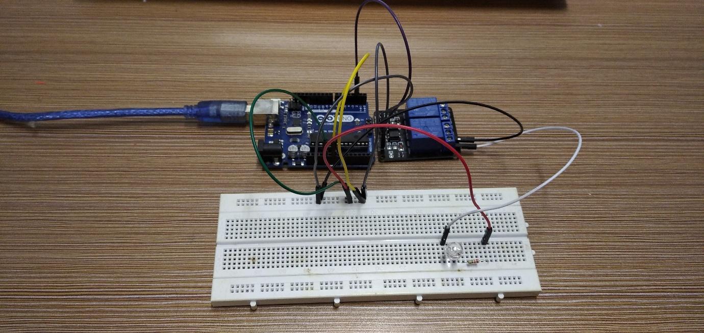
To demonstrate the working of the relay and how we can use relay to control the LED we have posted an images below:
Conclusion
Relays are the electrically controlled switches used for turning on and turning off the devices connected with it. Relays can be interfaced with microcontrollers using the Arduino boards and, in this way, there are a large number of devices that we can control using the relays. To demonstrate how relays can be used for controlling the devices we have interfaced a 2 relay module with Arduino and controlled an LED.