ESP32 is an IoT based microcontroller which can process multiple instructions just like Arduino, but it comes by default with Bluetooth and WiFi. ESP32 is a standalone board which can help other system to reduce their load because it can act as master or slave device. Like Arduino we can also interface an LCD screen with ESP32. Let’s discuss how to do this in detail.
Interfacing LCD with ESP32 using Arduino IDE
I2C LCD can display data processes during programming on a screen. It gives a visual representation of data received from sensors, modules, or microcontrollers. LCD can be integrated without using I2C module but the benefit of using I2C is it uses only two wires SDA and SCL to communicate data resulting in providing with several free I/Os on ESP32 that can be used to integrate other devices.

Additionally, it has a potentiometer on board that can control LCD display brightness by just adjusting the potentiometer knob.
Wiring the LCD to the ESP32 with I2C
Connect I2C module with ESP32 using pin digital pin 21 and 22 of ESP32. Below given image represents connections of I2C with ESP32 and LCD display. The SDA pin of I2C is connected with GPIO pin 21 of ESP32 and similarly SCL pin of I2C is joined with GPIO pin 22.
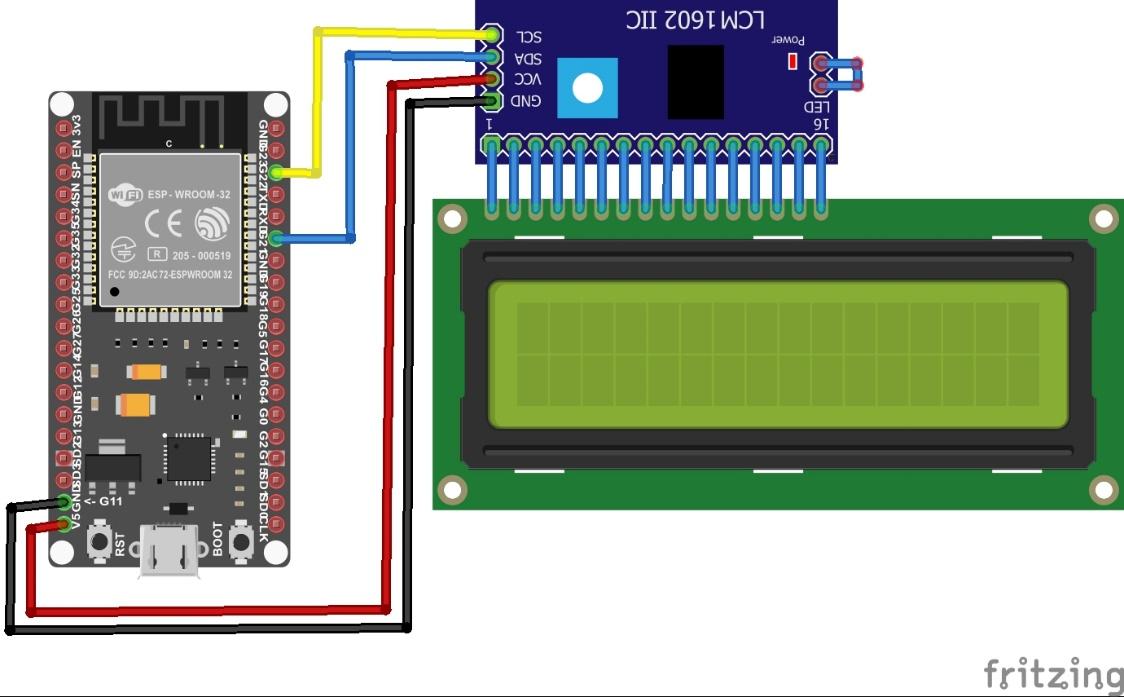
Table below represents the connection of ESP32 with I2C.
| I2C LCD | ESP32 |
| GND | GND |
| VCC | VIN |
| SDA | GPIO 21 |
| SCL | GPIO 22 |
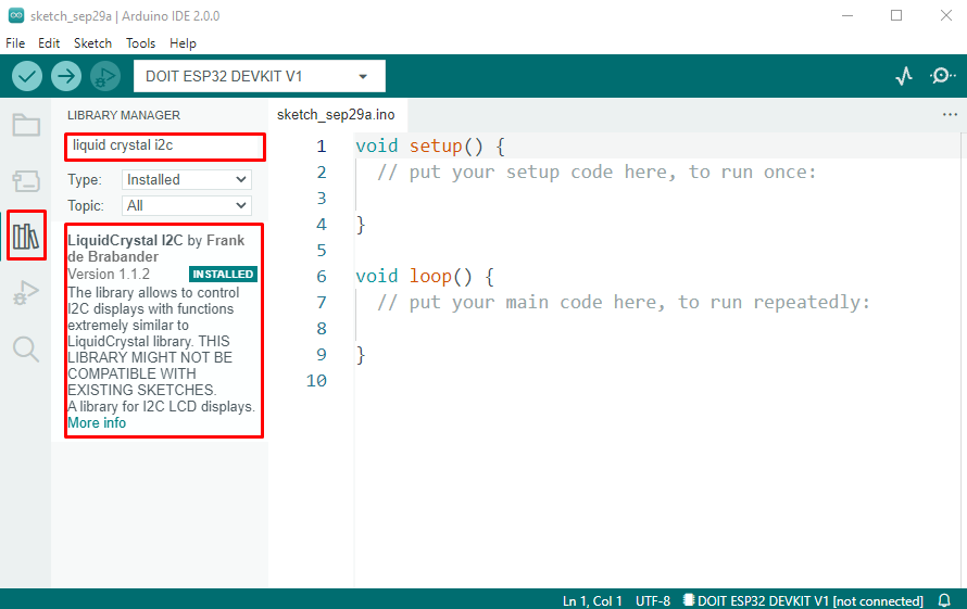
Installing the LiquidCrystal_I2C Library in Arduino IDE
Once the circuit is completed connect ESP32 board with PC. Now open the IDE and go to Library Manager search for Liquid Crystal I2C library. Install the library given by Frank de Brabander.
Once you click the install library files will begin downloading, upon successful installation you will receive a library installed message in the output window.
Getting the LCD Address
Before we connect any I2C device with ESP32 it’s important to note at which address that specific device is connected. Some modules have default I2C addresses written on while some of them have no instructions to check I2C addresses.
To solve this problem, we have a wire library code that checks for all I2C devices connected and at what address they are connected to ESP32. This will help in debugging and improving the ESP32 circuit.
void setup()
{
Wire.begin(); /*Wire I2C communication START*/
Serial.begin(115200); /*baud rate set for Serial Communication*/
while (!Serial); /*Waiting for Serial output on Serial Monitor*/
Serial.println("\nI2C Scanner");
}
void loop()
{
byte err, adr; /*variable error is defined with address of I2C*/
int number_of_devices;
Serial.println("Scanning.");
number_of_devices = 0;
for (adr = 1; adr < 127; adr++ )
{
Wire.beginTransmission(adr);
err = Wire.endTransmission();
if (err == 0)
{
Serial.print("I2C device at address 0x");
if (adr < 16)
Serial.print("0");
Serial.print(adr, HEX);
Serial.println(" !");
number_of_devices++;
}
else if (err == 4)
{
Serial.print("Unknown error at address 0x");
if (adr < 16)
Serial.print("0");
Serial.println(adr, HEX);
}
}
if (number_of_devices == 0)
Serial.println("No I2C device attached\n");
else
Serial.println("done\n");
delay(5000); /*wait 5 seconds for the next I2C scan*/
}
This code will help to find the number of I2C devices and their address at which they are connected. This code is commonly referred to as I2C Scanner code.
First, we included a “Wire.h” library. Then in the setup part of code we have begun this library. After that we initialize serial communication by defining baud rate 9600. This will help to see output over the serial monitor.
In the loop section, we defined two variables “err” and “adr”. Then we defined another variable “Devices” and set it to zero. After that a for loop is initialized with values between 0 and 127.
Next, we input the address to the wire using wire.beginTransmission(), the I2C scanner will look for the acknowledgment of devices and their address. The value read will be stored in the variable “error”. Return value will be equal to 0 if the device acknowledges the address otherwise value will become 4. Next, we have used an if condition which will print the I2C device address if the value is <16. Final address of the device is printed in Hexadecimal form.

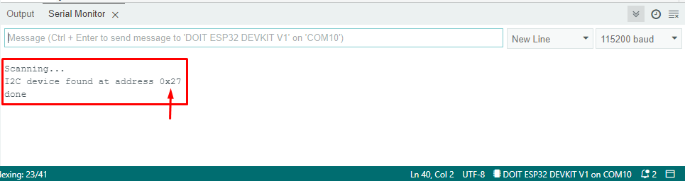
Output of devices attached to ESP32 over I2C protocols will look like as shown in diagram below. Here 0x3C is the address of the I2C LCD while 0X27 is the address of the OLED screen.
Displaying Text on the LCD
Displaying text on an LCD using ESP32 is very simple. All we need is to select the row and column of LCD where we want to display characters. Below is a very simple Program displaying “Linuxhint ESP32”.
/* Initialize LCD columns and rows*/
int lcd_Columns = 16;
int lcd_Rows = 2;
/* set LCD address, number of columns and rows*/
/* To know about I2C address (0x27), run an I2C scanner sketch*/
LiquidCrystal_I2C lcd(0x27, lcd_Columns, lcd_Rows);
void setup(){
/* initialize LCD*/
lcd.init();
/* turn on LCD backlight*/
lcd.backlight();
}
void loop(){
/*set cursor to first column, first row*/
lcd.setCursor(0, 0);
/* print message*/
lcd.print("Linuxhint ESP32");
delay(1000);
/*clears the display to print new message*/
lcd.clear();
}
While writing code the first thing we need is to call the Liquid crystal library we installed.
Next two lines represent the rows and columns of the LCD where we need text to display. If you are using a display of any other size, then change the row and column accordingly.
int lcd_Rows = 2;
Then we will display the I2C address at which the LCD I2C module is connected. In our case it is 0x27. If you are using a similar version of LCD, it may be the same as ours otherwise run the address checking code given above.
Next, we initialized the display and backlight of the LCD using the following commands.
lcd.backlight();
To display text LCD cursor command is used 0 corresponds to the first column and row.
After that, the lcd.print() function is used to display text, then we clear the screen using lcd.clear().
lcd.clear();

Output
Output of code represents characters defined in the program on LCD display.

Conclusion
We covered all the steps to connect an LCD display with ESP32 using the I2C module. To connect the LCD, we need to install the library first using the library manager. Then using the correct I2C address we can send any data we want to the LCD.