Liquid Crystal display
Liquid crystal display is the module that can be used to display the outputs of an Arduino program. The display modules come with different sizes, and it depends on the choice of the user. Mostly the resolution of 16×2 is used which has 16 pins in total.
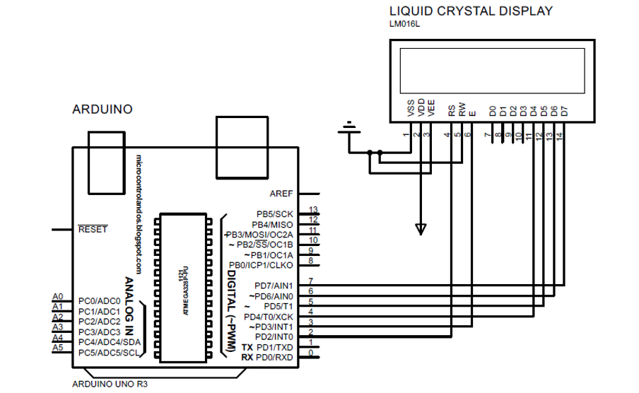
There are 8 pins for receiving the data (D0 to D7); pin 3 (VEE) is used for setting the contrast of the display , pin 6 (E) for enabling the display and it always remains in HIGH state when connected to Arduino. Moreover, pin 5 (RW) is used for reading output of the Arduino or also for writing purposes and pin 4 (RS) is used for selection of the register. To provide supply to the liquid crystal display the pin 2 (VDD) is used and 1 is kept ground while interfacing.

This Liquid crystal display has two registers one is for the data and other is for the command and if the state of the pin for register selection is 0 then it means that it has selected the command register. The command registers control the display module by using multiple commands like clearing the screen, like initializing the display and many more.
The data register on the other hand only stores the data in the form of ASCIIs that is to be displayed on the module. When the data register is selected by the module the pin will always be in the HIGH state that is 1.
Interfacing liquid crystal display (LCD) with Arduino
To interface the display with Arduino first the library for the LCD is defined and then the pins of Arduino are to be initialized which are to be connected to the display.
The pins for the display are initialized using the LiquidCrystal lcd() function which has six arguments. The first argument is the pin of Arduino to which the enable pin of the display is connected and the second argument is the Arduino pin to which the register selection pin of display is connected. The rest of the four Arduino pins given are connected to the four data pins of the display.
Then a function of lcd.begin() is used for initializing the dimensions for the display and then output for the program is printed using lcd.print() function
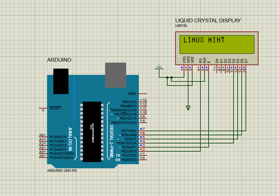
For illustration purposes a simulation for displaying the output of an Arduino board LCD is made and the Arduino code for the respective simulation is also given. Here in the simulation the pin 2 of Arduino is connected to the enable pin and pin 3 of Arduino board is connected to the register selection pin of the liquid crystal display. Similarly, the data pins of the LCD are connected to the pins 4,5 6 and 7 of Arduino.
In the setup function the dimensions of the LCD module are initialized using the lcd.begin () function. So,here only 16 columns and 2 rows are used for displaying the data using the lcd.print() function.
LiquidCrystal lcd(2, 3, 4, 5, 6, 7);
void setup () {
lcd.begin(16, 2);
lcd.print("LINUX HINT");
}
void loop() {
Conclusion
The Liquid crystal display (LCD) is the module used for displaying the outputs. It is one of the key components to visually display the output of the data received from various sensors connected with Arduino. In this write-up the process of interfacing liquid crystal display with Arduino is explained and a simulation of 16×2 LCD interfaced with Arduino Uno board is also provided with code.