Interfacing buzzer with Raspberry Pi
Here, you will learn to do a simple project on how to interface buzzer with your Raspberry Pi device. Before starting this project, make sure that you will have necessary components which are as follows.
- Raspberry Pi 4
- Breadboard
- Buzzer
- Wires to connect Raspberry Pi GPIO Pins with the breadboard
- Resistor
After ensuring that all the components are available, you can then start creating your project and below are the two methods to do it wisely.
Assembling hardware
Firstly, we will assemble the components on breadboard:
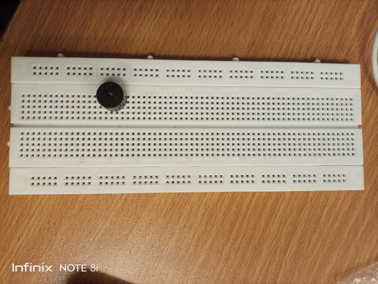
Step 1: Put the buzzer onto the breadboard as shown below in the image. The one leg of the buzzer takes the input from the Raspberry Pi and the other will connect to the ground.
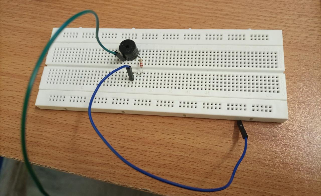
Step 2: Connect the cable to both ends of the buzzer placed on the breadboard.
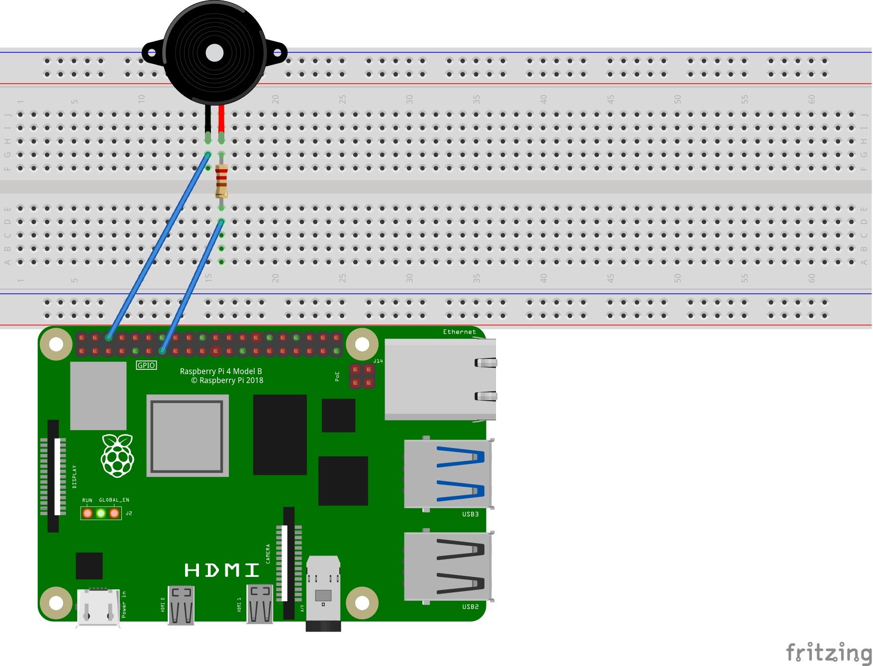
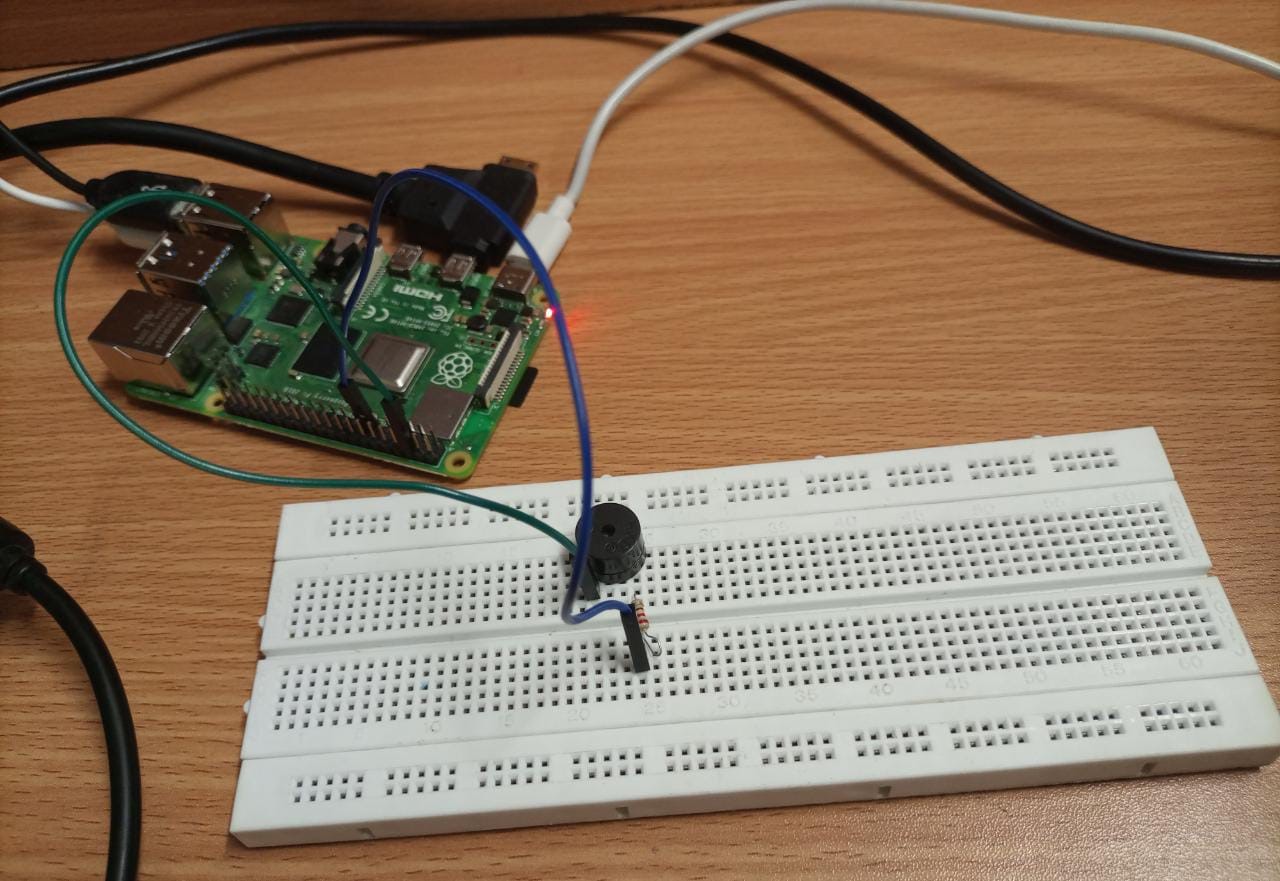
Step 3: Now we have two jumper wires, the blue one and the green one and you will need to ensure that the green wire is connected to GPIO 6 (Ground Pin) and the blue wire is connected with GPIO 27 (Interfacing).
Interfacing buzzer with Raspberry Pi using Scratch Desktop
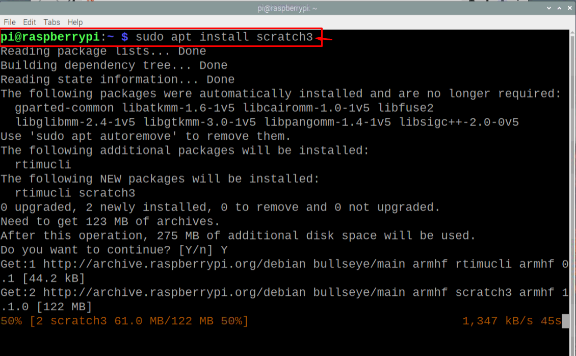
After establishing the connection, you will need to download a software called Scratch Desktop on Raspberry Pi 4 using the below mentioned command in the terminal.
After the installation, the below are the steps which will need to be performed in order to successfully interface buzzer with Raspberry Pi and produce a sound.
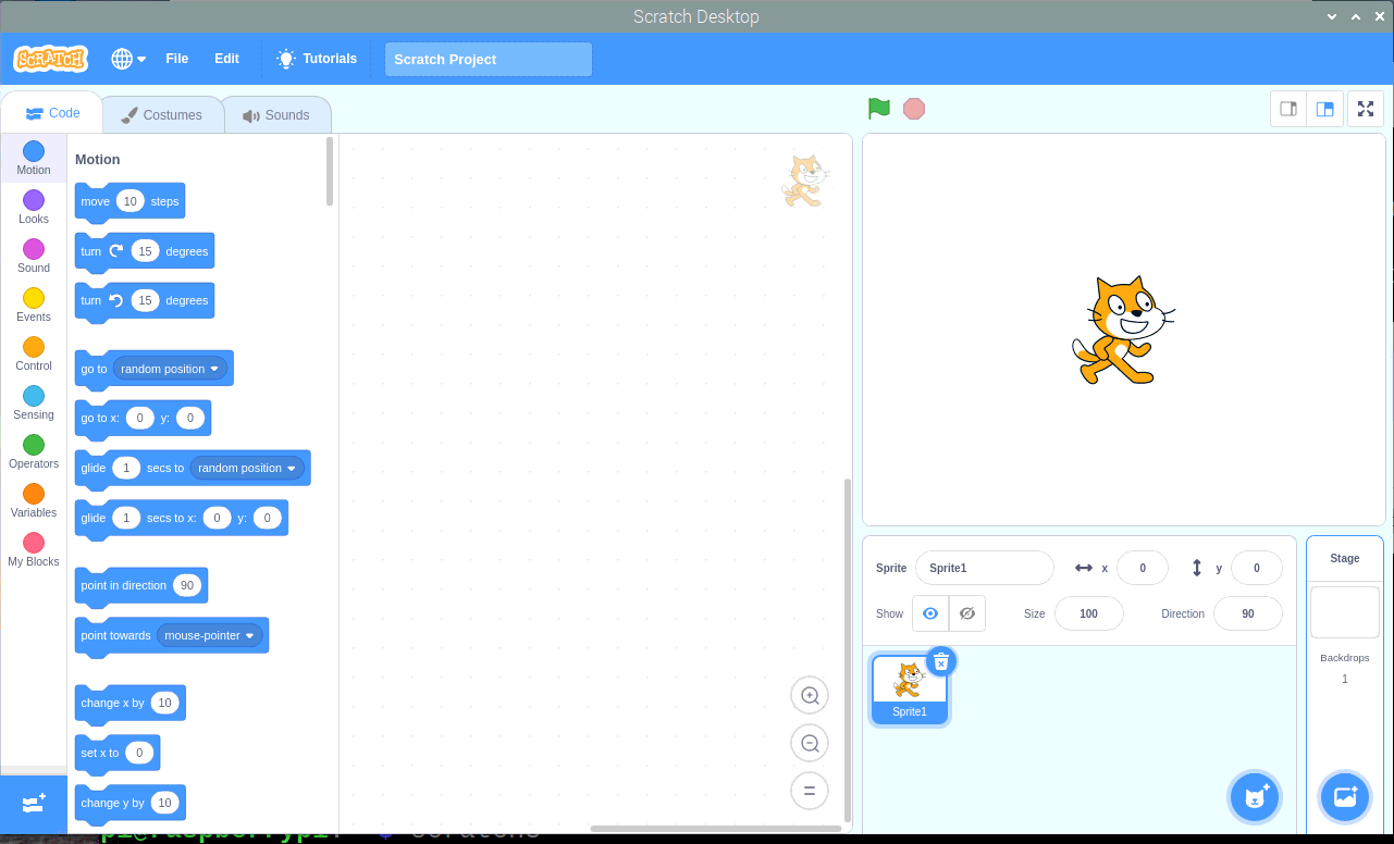
Step 1: Now run the scratch desktop by entering the command “scratch3” in the terminal.
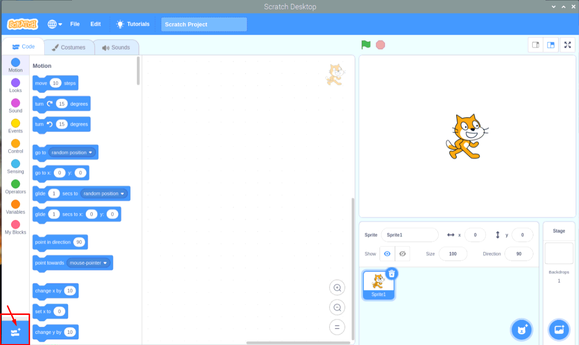
Step 2: Now go to the “Add Extension” option in the scratch desktop as shown below.
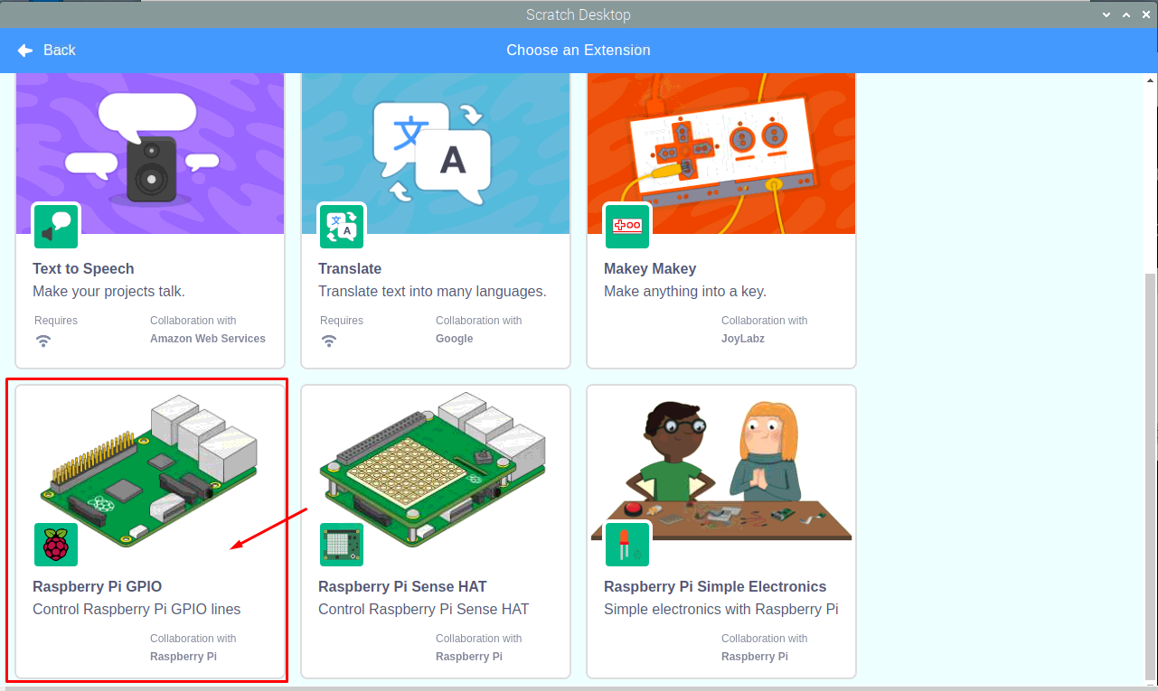
Step 3: Scroll down and select the “Raspberry Pi GPIO” option.
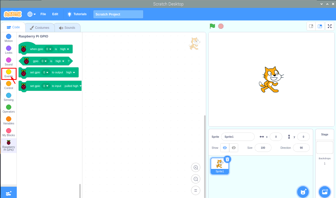
Step 4: Click on the “Events” option.
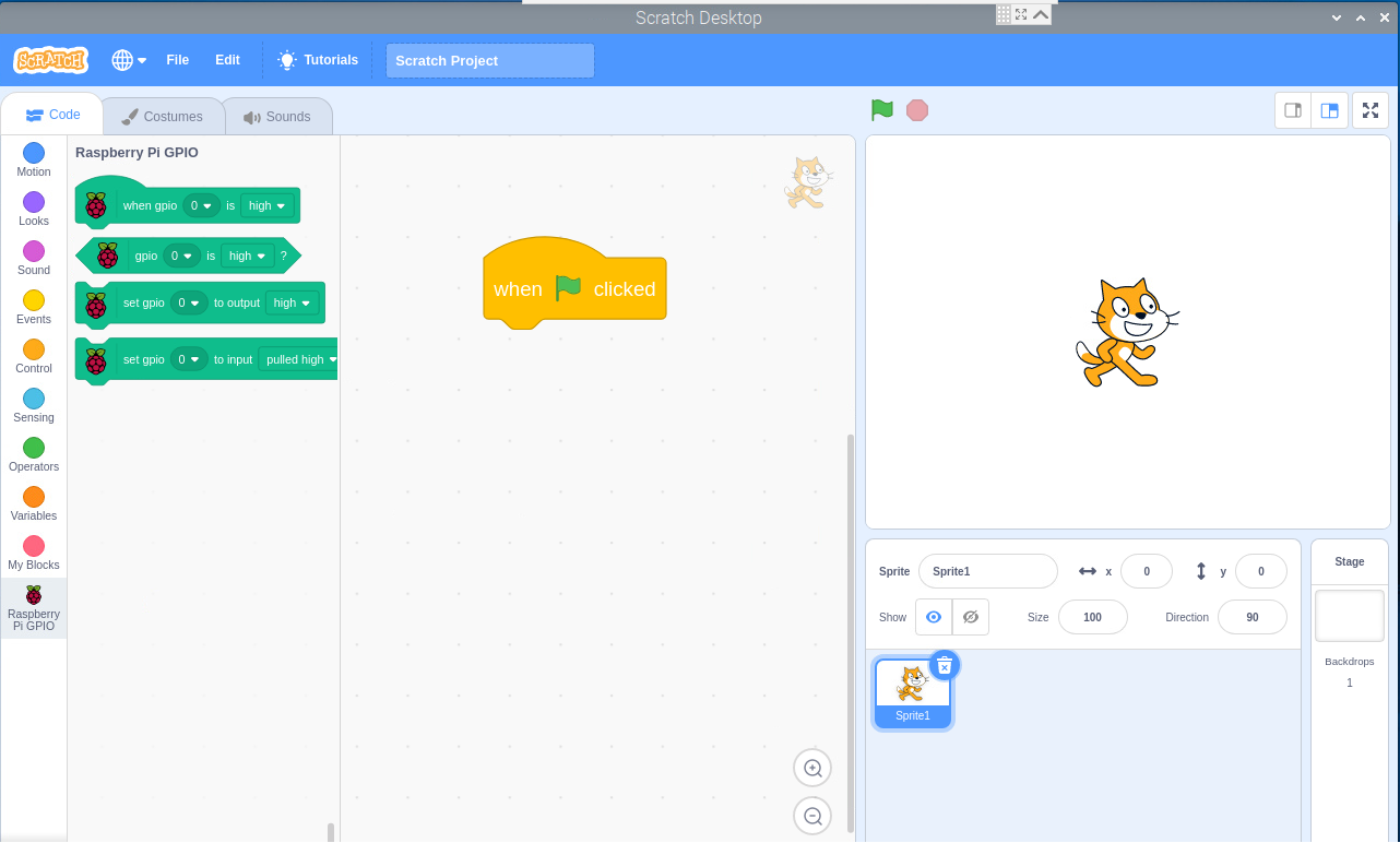
Step 5: Drag the “When – Clicked” event block into the other box as shown in the image below.
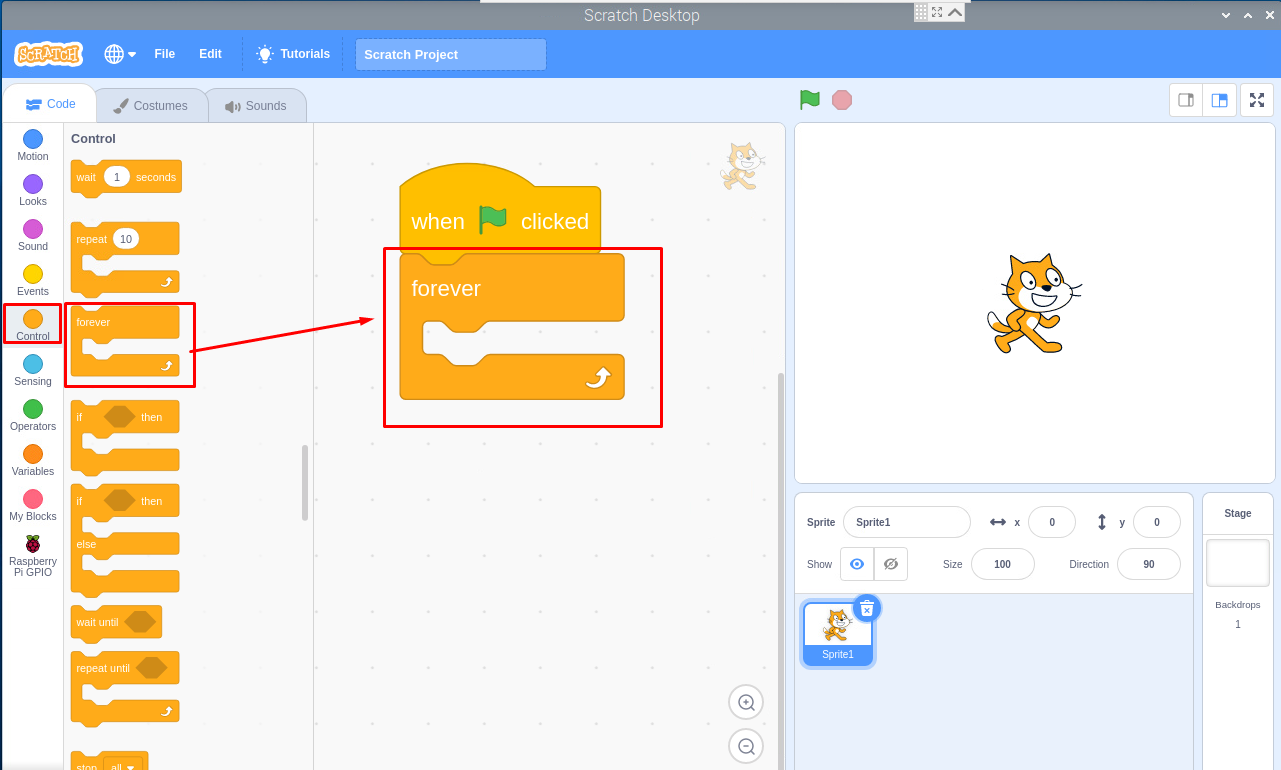
Step 6: Next, go to the “Control” option and drag the “forever” into the next box as shown below.
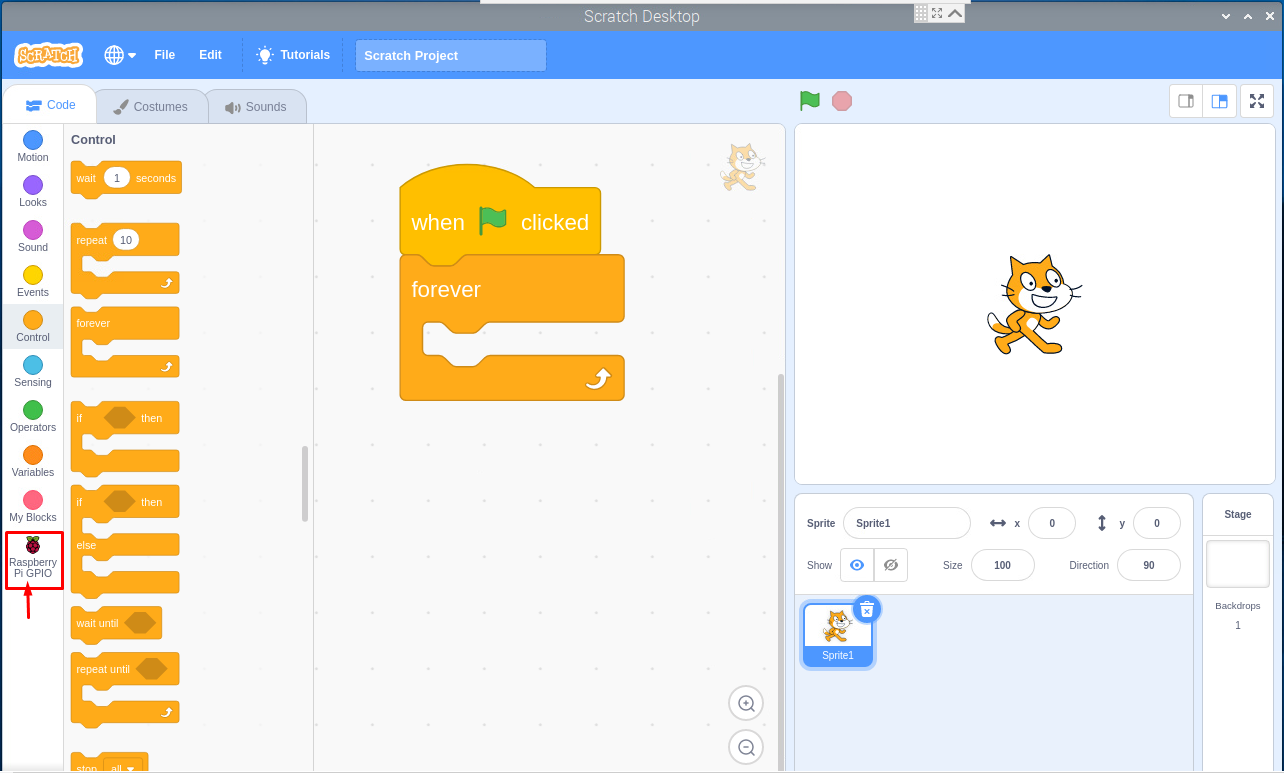
Step 7: In the next step, go to the “Raspberry Pi GPIO” option.
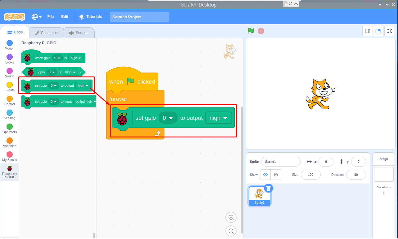
Step 8: Drag the “Set GPIO high” to the next box onto the “forever” box as shown below.
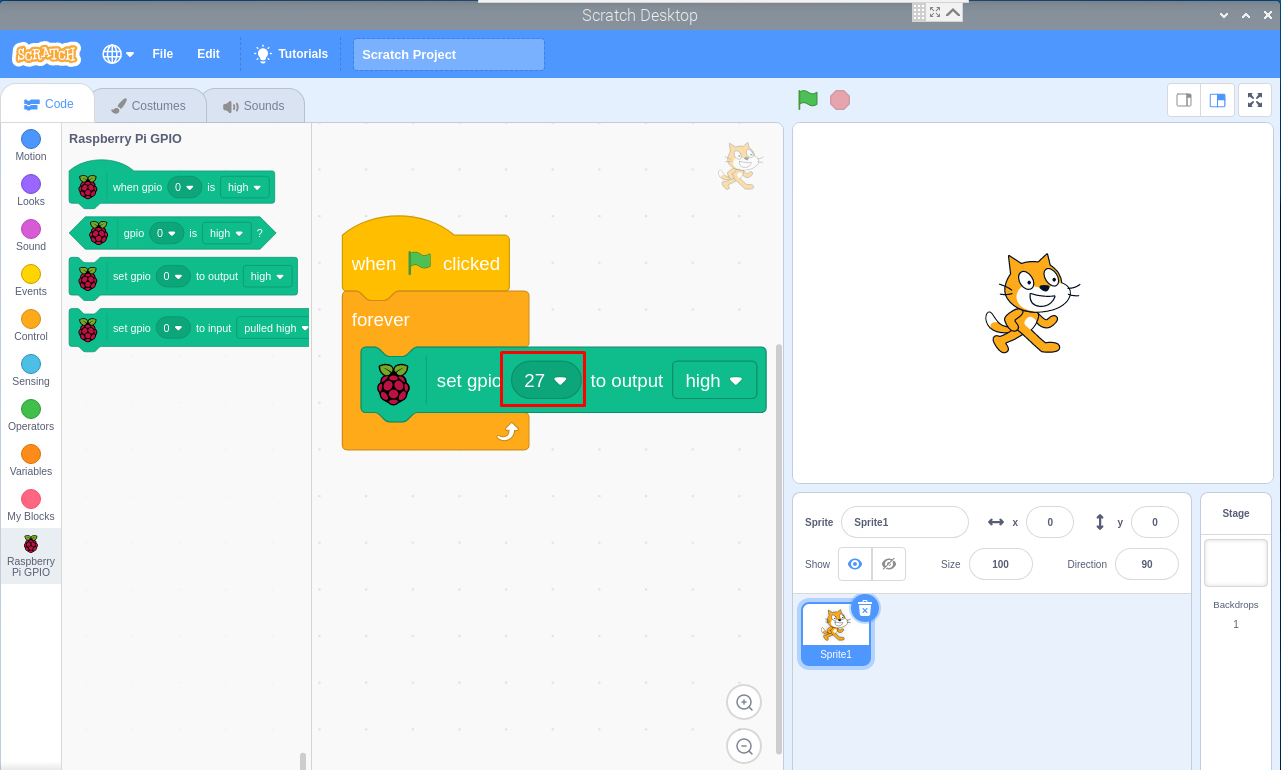
Step 9: Now set the GPIO pin to number 27 from 0 as shown below.
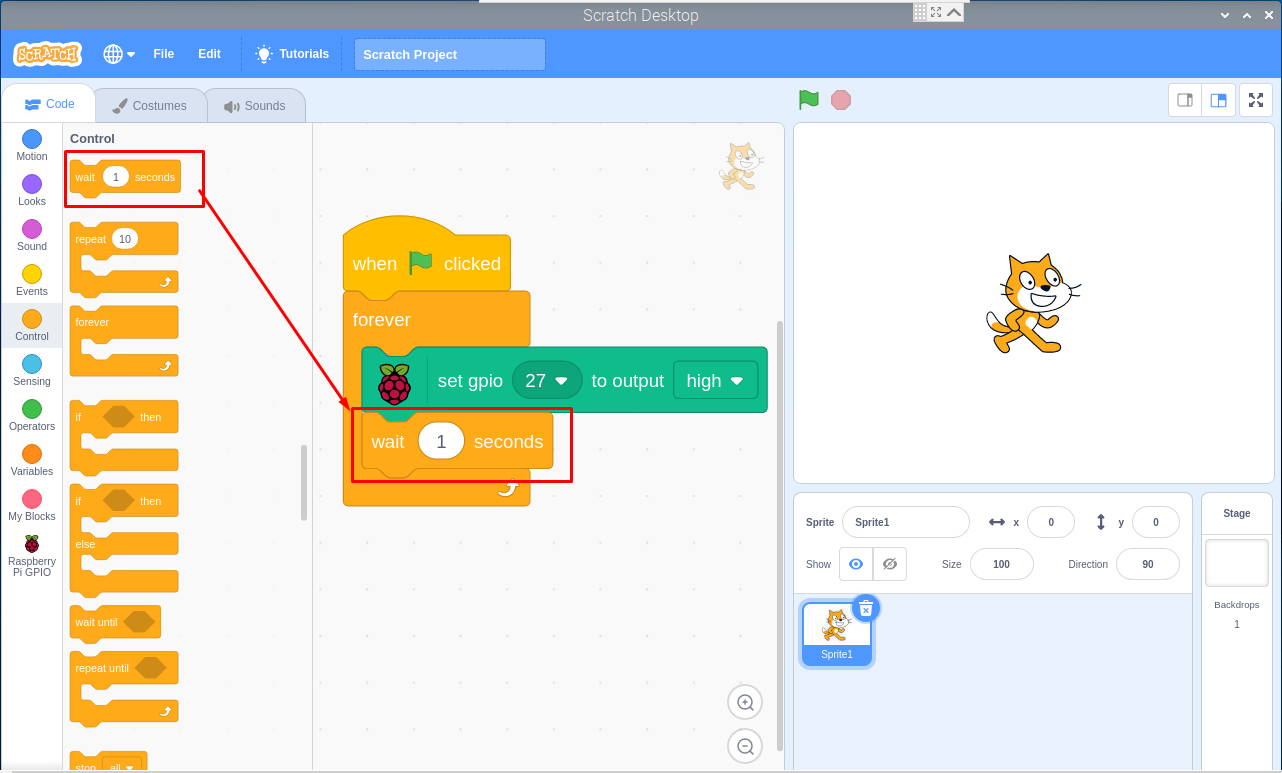
Step 10: Next, go to the “Event” option again and in the “Control” option, select “wait 1 seconds” and placed it below the set “gpio” box as shown below.
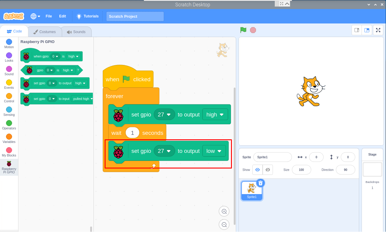
Step 11: Go to “Raspberry PI GPIO option again” and there again select the “set gpio” box and place it after the “wait 1 seconds” box but this time change the output from high to low.
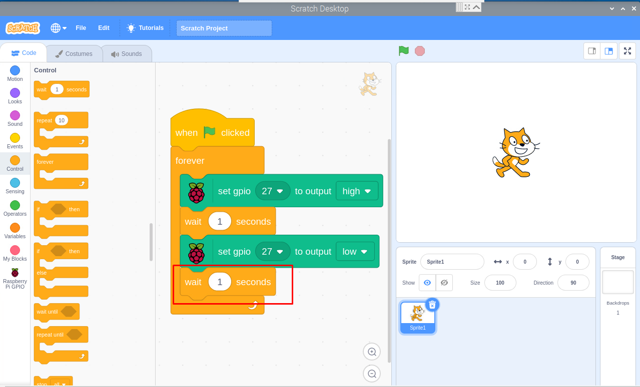
Step 12: Go to the “Control” option again and select again the “wait 1 seconds” box. Drag the box and place it below the low output gpio box as shown below.
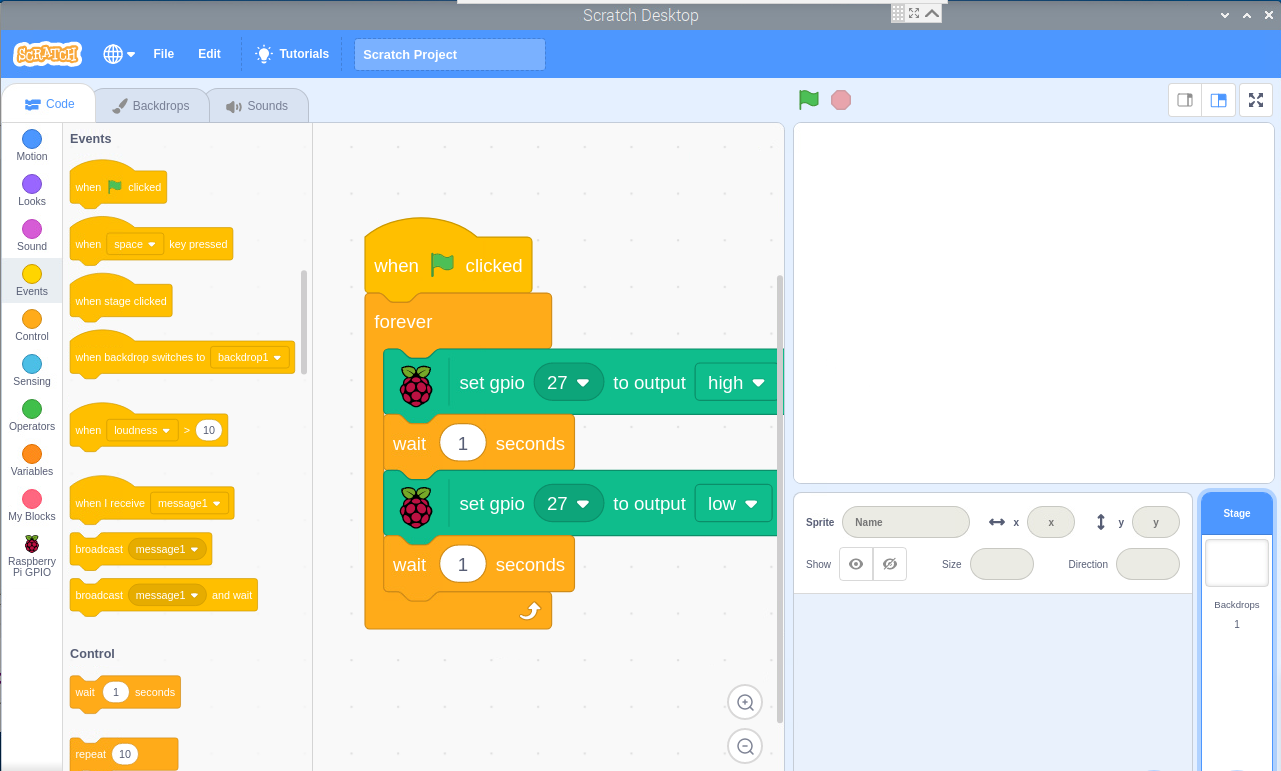
Step 13: Press the “Red button” and there you go your buzzer will start to beep.
Interfacing buzzer with Raspberry Pi using Python Code
You can also interface buzzer with Raspberry Pi using a simple python code, below is the circuit you will first need to build. GPIO6 is used as a ground pin while GPIO27 is used for interfacing.
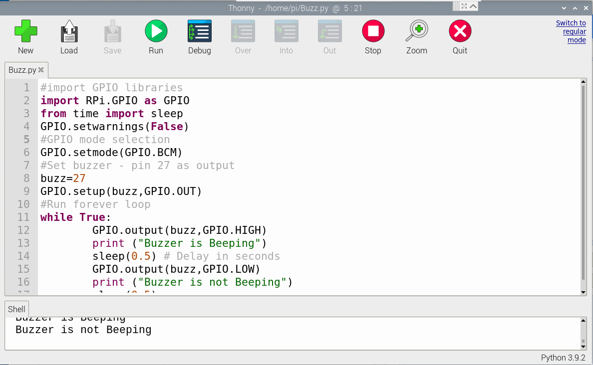
After successfully creating the circuit and connecting it with the Raspberry Pi 4, the next step is to open the Thonny IDE and write down the below code in it.
import RPi.GPIO as GPIO
from time import sleep
GPIO.setwarnings(False)
#GPIO mode selection
GPIO.setmode(GPIO.BCM)
#Set buzzer - pin 27 as output
buzz=27
GPIO.setup(buzz,GPIO.OUT)
#Run forever loop
while True:
GPIO.output(buzz,GPIO.HIGH)
print ("Buzzer is Beeping")
sleep(1) # Delay in seconds
GPIO.output(buzz,GPIO.LOW)
print ("Buzzer is not Beeping")
sleep(1)
Run the code in the IDE and you will get the output as well as the buzzer will beep every 1 seconds until you stop it from the IDE when it is beeping.
Conclusion
Interfacing buzzer with Raspberry Pi on Scratch Desktop is incredibly easy for the beginners who don’t have enough understanding of the Python language. But for those who are eager about learning the Python code, they will choose the second method to interface buzzer with Raspberry Pi. Both ways will be done in a few minutes if you have successfully built the circuit on a breadboard.

