Creating a home security system using Arduino Uno
The security system is always based on some type of authorization and that authorization can be in the form of pass code, fingerprint, voice recognition and facial recognition. In this project we have designed a security system that uses a password for the authorization. The following are the components that we have used to make a security system.
- Arduino Uno
- Breadboard
- Connecting wires
- 4×4 membrane keypad
- 16×2 Liquid crystal display (LCD)
- RGB module
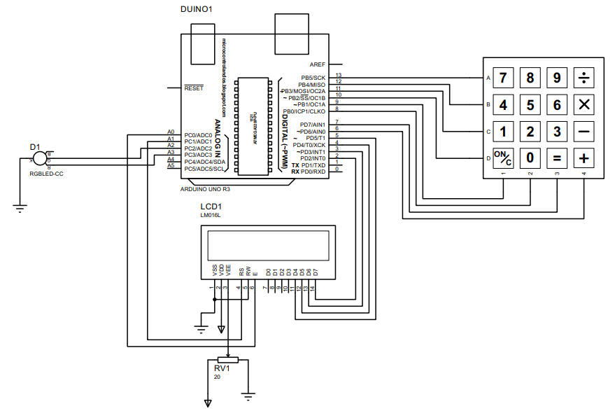
The image for the schematic of creating a home security system using Arduino s posted below:
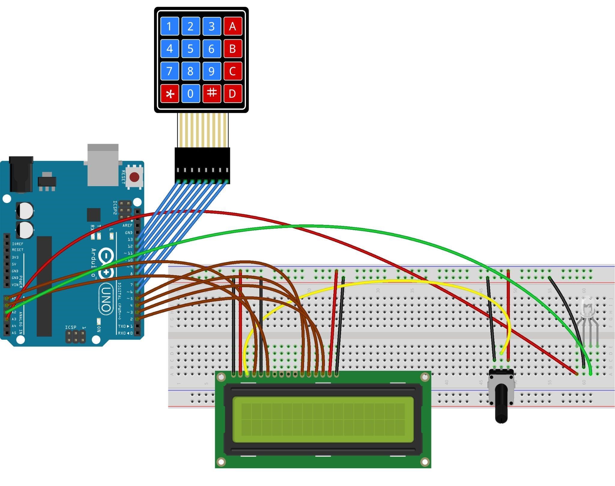
Hardware Assembly for creating the home security system
For assembling the hardware, we have connected the components in such a way that first of all we have placed the LCD and potentiometer on the breadboard. Further we have posted an image below for the assembling of the hardware for the security system.
The brown wires interface the LCD with the Arduino, and the blue wires connect the keypad with Arduino and to adjust the brightness 0f the LCD the yellow wire connects the potentiometer with LCD.
We have used the RGB module to display the status of the authorization when the password is entered and the color of the wires shows the color of LEDs used for indication.
Arduino code for the home security system
The Arduino code compiled for the home security system is given below:
#include <Keypad.h> // defining the library for keypad
LiquidCrystal lcd(A1, A0, 5, 4, 3, 2);// Arduino pins for LCD
#define Password_Length 9 // defining the password length
char userInput[Password_Length];/*string for storing the user input*/
char Master[Password_Length] = "1234"; /*saving the correct password*/
char customKey;// This variable holds key input of every key pressed
byte pressCount = 0;/* for storing the counter for the amount of times the keys are pressed*/
const byte ROWS = 4; // defining number of rows
const byte COLS = 4; // defining number of columns
int led = A2;// Arduino pin for green LED
int led2 =A3;// Arduino pin for red LED
char keys [ROWS] [COLS]= // assigning values to keys of the keypad
{
{'1', '2', '3', 'A'},
{'4', '5', '6', 'B'},
{'7', '8', '9', 'C'},
{'*', '0', '#', 'D'}
};
// C key is used for CLEAR and A key is used to ENTER the password
byte rowPins[ROWS] = {13,12,11,10}; //Arduino pins for rows of keypad
byte colPins[COLS] = {9,8,7,6}; // Arduino pins for columns of keypad
Keypad customKeypad = Keypad( makeKeymap(keys), rowPins, colPins, ROWS, COLS );// mapping the values to the respective keys of keypad
void setup() {
lcd.begin(16,2);// initializing the dimensions of LCD
lcd.setCursor(0,0);// setting the place for the data to be displayed
lcd.print(" Arduino Home ");// data to be displayed
lcd.setCursor(0,1);// setting the place for the data to be displayed
lcd.print(" Security System");// data to be displayed
delay(2000);// time for which the data will be displayed
lcd.clear();// clearing the LCD
pinMode(led,OUTPUT);
pinMode(led2,OUTPUT);
digitalWrite(led2,LOW); //assigning LOW state to Red LED
}
void loop() {
lcd.setCursor(0,0); //setting the place for the data to be displayed
lcd.print("Enter Password:"); //asking for entering the password
customKey = customKeypad.waitForKey(); // waiting for the user to enter the password
if (customKey != NO_KEY && customKey != 'C' && customKey != 'A') /* If key other than clear function and equal to function is pressed*/
{
userInput[pressCount] = customKey;/* count the keys with the integer values pressed */
lcd.setCursor(pressCount + 4, 1); /*setting the place where the password will be displayed on LCD*/
lcd.print("*"); // displaying the Asterisk against each password key
pressCount++; // increment one in the count of length of password that is 4
}
else if (customKey == 'C') // if the key having clear function C is pressed
{
lcd.clear();// then clear the LCD
clearData();
}
else if (customKey == 'A') /* if the key is pressed and the password count is less than 4 then clear the LCD and display invalid password*/
{
lcd.clear();
lcd.setCursor(0,0);
lcd.print("Invalid Password!");// display its an invalid password
delay(2000);
clearData();
}
if (pressCount == 4) /*if the 4 value password is entered then match the user input with given password */
{
lcd.clear();
waitHere(); // function that displays the password in asterisk
}
}
void waitHere(){
lcd.setCursor(0,0);
lcd.print(" Enter Password:");
lcd.setCursor(0,1);
lcd.print(" ****");
customKey = customKeypad.waitForKey(); // waiting for the user to press the equal to key
if (customKey != NO_KEY && customKey == 'A') /*if the enter key is pressed the program will match the password entered by the user*/
{
lcd.clear();
lcd.setCursor(0,0);
if (!strcmp(userInput, Master)) // user input is matched then grant the access
{
lcd.setCursor(0,0);
lcd.print("ACCESS GRANTED");
digitalWrite(led,HIGH);// turn the green LED on
delay(1000);
clearData();
}
else if (strcmp(userInput, Master)) /*if password is not matched then deny the access*/
{
lcd.setCursor(0,0);
lcd.print("ACCESS DENIED");
digitalWrite(led2,HIGH);//turn the red LED on
delay(2000);
clearData();
}
}
/* conditions for each key pressed on the keypad for each key other than clear and enter the wait here function is used to display it on LCD*/
if (customKey != NO_KEY && customKey == 'C')
{
lcd.clear();
clearData();
}
if (customKey != NO_KEY && customKey == '0')
{
waitHere();
}
if (customKey != NO_KEY && customKey == '1')
{
waitHere();
}
if (customKey != NO_KEY && customKey == '2')
{
waitHere();
}
if (customKey != NO_KEY && customKey == '3')
{
waitHere();
}
if (customKey != NO_KEY && customKey == '4')
{
waitHere();
}
if (customKey != NO_KEY && customKey == '5')
{
waitHere();
}
if (customKey != NO_KEY && customKey == '6')
{
waitHere();
}
if (customKey != NO_KEY && customKey == '7')
{
waitHere();
}
if (customKey != NO_KEY && customKey == '8')
{
waitHere();
}
if (customKey != NO_KEY && customKey == '9')
{
waitHere();
}
}
// function assigned to key C of keypad for clearing the LCD
void clearData() {
while (pressCount != 0)
{
userInput[pressCount--] = 0; // decrements the value entered to zero
digitalWrite(led,LOW);
setup(); // calling the setup function to restart the program
}
}
We have given the password in the code and the program simply takes the input from the user and matches the password. This program checks the password in two ways, one by checking the length of the password and then it matches both passwords saved in the string.
If the passwords are correct, then the program will give the access and turn on the green LED whereas if the password is incorrect then it will deny the access and the red LED will turn on.
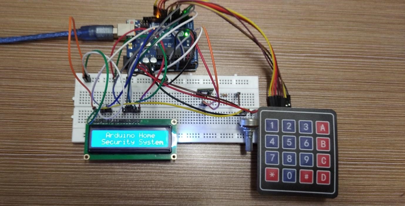
Hardware implementation of home security system using Arduino Uno
The image posted below shows the starting of the Arduino code for the home security system. Furthermore, we have posted the images of the Arduino code in the same sequence in which the code runs.
In the figure below the code is asking for the password and we have given the passcode using the keypad.
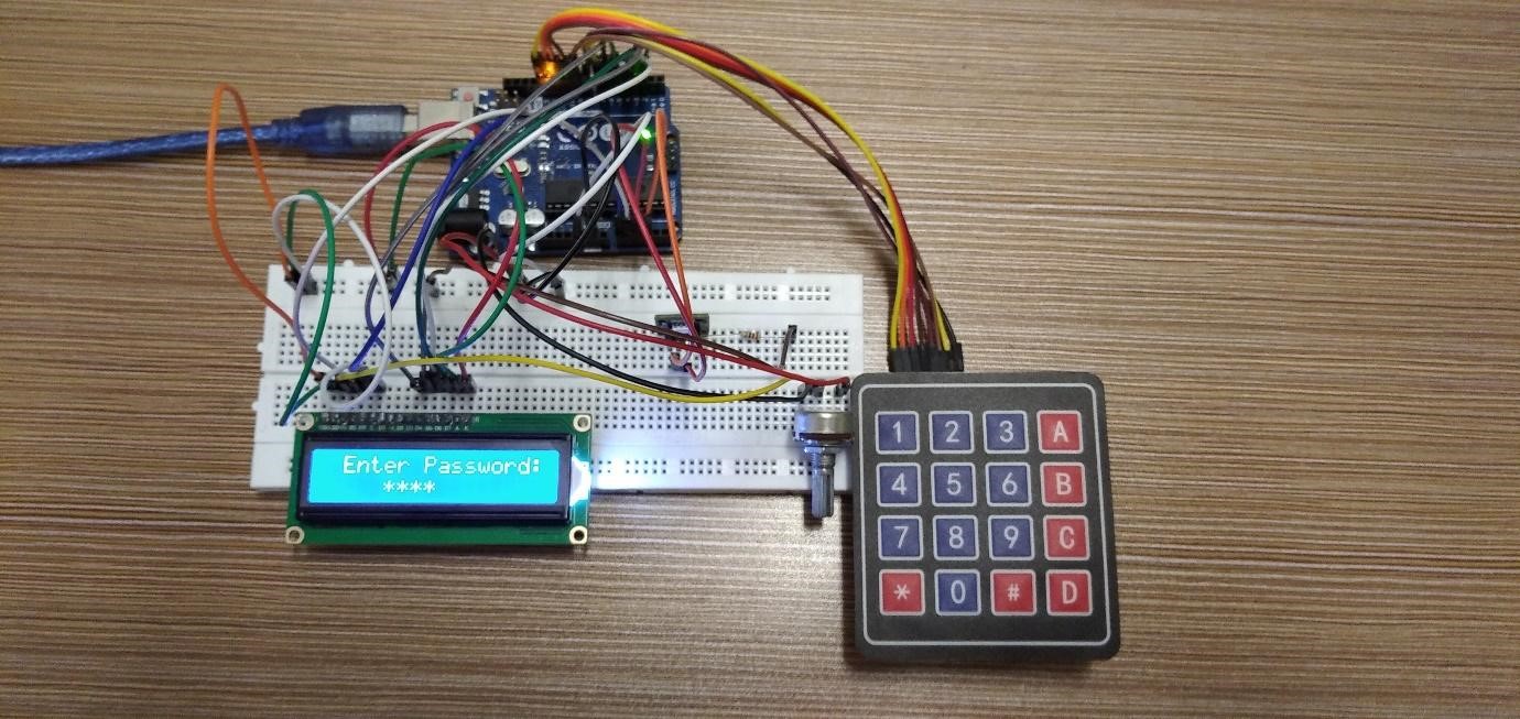
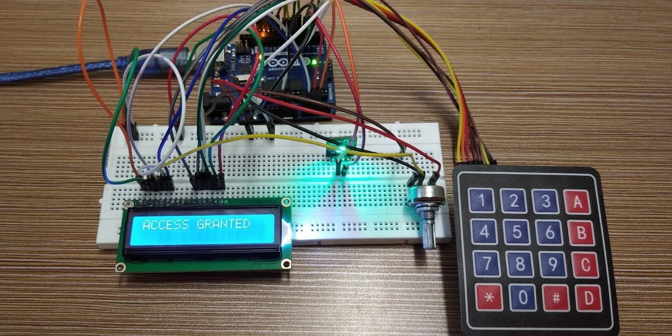
Next, we have pressed the key A on the keypad to enter the password and the password is correct, so green LED is turned on which means the access is granted.
Similarly, if the password is not correct then the red LED will turn which means that authorization is not given.

Conclusion
To make beginner or advance level projects the Arduino platform will be a great choice as it allows the users to create circuits the easy way. There are a wide variety of do-it-yourself projects that can be made using Arduino. A home security system is made in this write-up , a keypad is used to get the password where the RGB module is used for indication of the access.