
Raspberry Pi 4 has come up with more advanced features than the previous Raspberry Pi model. It was launched in June 2019 and has come up with a much-improved processing speed of about 90% as compared to the previous version due to the inclusion of 4GB and 8GB RAM memory. Its General-Purpose Input Output (GPIO) pins have also maintained the previous standard set by the Raspberry Pi models, and are now more functional and performing flawlessly.
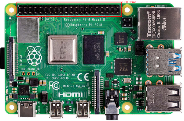
The Raspberry Pi 4 has 40 GPIO pins that can be configured to read inputs or write outputs. If you are unfamiliar with the operation of these GPIO pins, this article will assist you in understanding the operation of each pin.
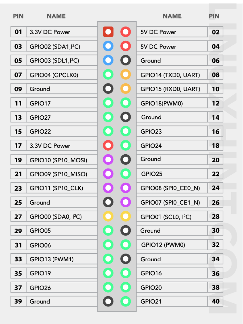
Raspberry Pi 4 GPIO Pins
Here, you will be able to learn the functioning of each pin, which helps you to do things on your Raspberry Pi 4. There are 40 pins in this model and among them, 26 are GPIO pins.
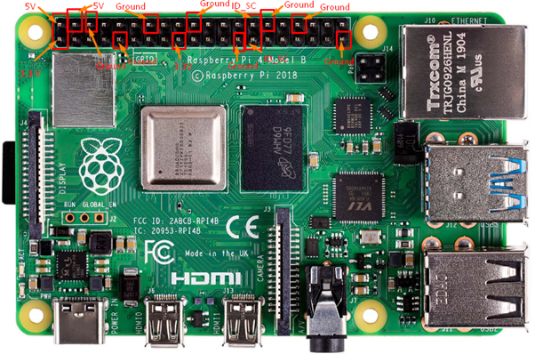
The Raspberry Pi model includes two 5V pins, two 3.3V pins, eight ground pins and two reserved pins.
5V pins: The 5V pins are used to output the 5V power supply provided by the Type-C port. The pins are numbered 2 and 4 on the Raspberry Pi 4 device.
3.3V pins: The 3.3V pins provide a 3.3V power supply to the external components, numbered 1 and 17.
Ground pins: The ground pins are used to close the electric circuits. The ground pins help you to protect your board from burning and play an important part in a circuit. The ground pins are numbered 6,9,14,20,25,30,34 and 39.
Reserved Pins: These pins are used to perform communication between I2C and EEPROM. If you are new to Raspberry Pi, you are advised not to connect anything with these pins, which are 27 and 28 number pins.
GPIO Pins
These are the pins on your Raspberry Pi that perform various functions and each pin is assigned a different task. Some pins are used as inputs, while others are used as outputs. Input voltages ranging from 1.8V to 3V are considered high voltage, while voltages less than 1.8V are considered low voltage. You need to keep the voltage of the power supply below 3V to protect your Raspberry Pi from burning.
The GPIO pins built on Raspberry Pi devices are used to perform various functions and their details are given below.
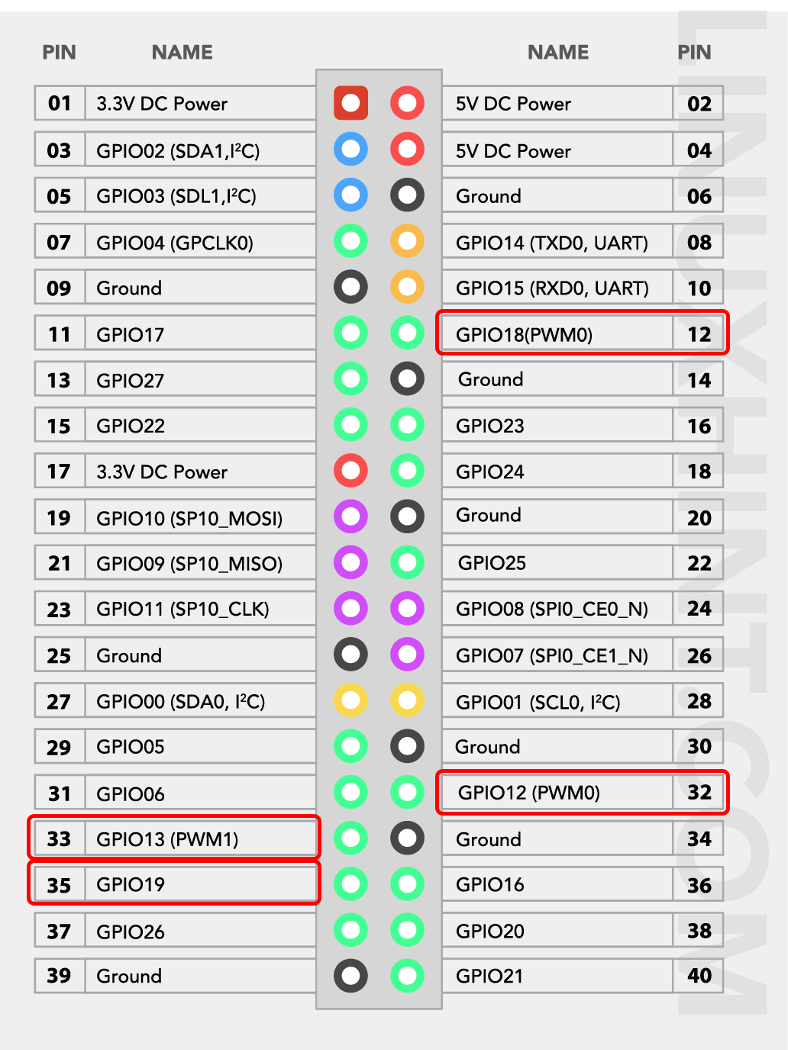
Pulse Width Modulation
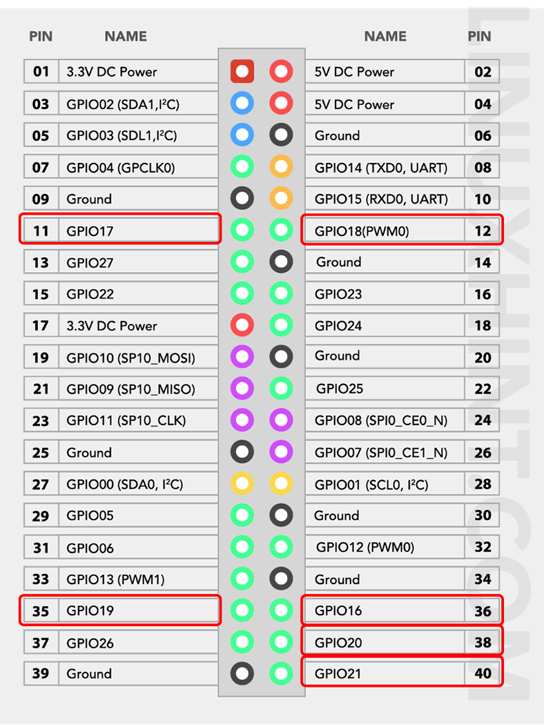
The GPIO pins are used for Pulse Width Modulation (PWM), which is the process of converting a Digital signal to an Analog signal. All pins can perform software PWM, but only a few can perform hardware PWM, including GPIO pins 12, 13, 18, and 19.
Serial Peripheral Interface Pins on Raspberry Pi 4
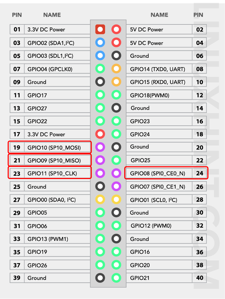
You can use Serial Peripheral Interface (SPI) pins to communicate between devices such as sensors or actuators on the Raspberry Pi. The Raspberry Pi sends data to a device via the Master Out Slave Pin (MOSI), and the same device communicates with the Raspberry Pi via the Master In Slave Out (MISO) pin. SP communication necessitates using five GPIO pins for GND, SCLK, MOSI, MISO, and CE. The CE pin is used to enable or disable circuit integration, whereas the SCLK pin serves as a clock for SPI communication. The Raspberry Pi’s SPI communication pins are listed below.
For SPIO select GPIO9 as MISO, GPIO10 as MOSI, GPIO11 as SCLK, GPIO8 as CE0 and GPIO7 as CE1.
For the case of SPI1 pins, select GPIO19 as MISO, GPIO20 as MOSI, GPIO21 as SCLK, GPIO18 as CE0, GPIO17 as CE1, and GPIO16 as CE2.
Inter-Integrated Circuit Pins on Raspberry Pi 4
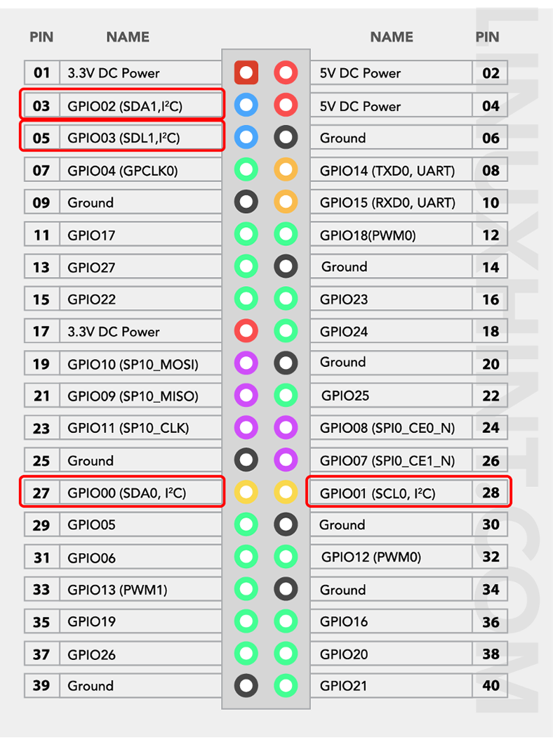
Using the Inter-Integrated Circuit (I2C) pins, the Raspberry Pi can control other peripheral devices attached to it. The communication is possible using the pins Serial Data (SDA) and Serial Clock (SCL). The data is forwarded using the SDA pin and the processing speed of data is controlled using the SCL pin. There is another type of data called “Electrically erasable programmable read-only memory (EEPROM)” data, which is in small quantities.
In Raspberry Pi, the GPIO2 pin is responsible for transferring data using SDA, and GPIO3 controls data speed by working as SCL. For the case of EEPROM, the GPIO0 pin is used for data transferring while the GPIO1 pin is used as a clock to control the speed of data.
UART Pins on Raspberry Pi 4
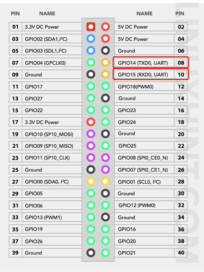
A Universal Asynchronous Receiver Transmitter (UART) is a type of communication in which data is transferred sequentially bit by bit. You need a transmitter and a receiver to perform UART communication. For UART communication, the Raspberry Pi 4 has two default pins. The GPIO14(TX) pin is a transmitter to send data to another device, while the GPIO15(RX) pin is a receiver to receive data from another device.
There are four more additional pins you can use for UART communication. However, you should need to enable them to use them. Among these pins, three are of type PL011 (main UART for models without Bluetooth) while the UART1 is of type mini UART (UART for models with Bluetooth). The following is the list of pins that are using UART communication:
| UART | GPIO Pins (TXD/RXD) |
| 0 | 14/15 |
| 1 | 14/15 |
| 2 | 0/1 |
| 3 | 4/5 |
| 4 | 8/9 |
| 5 | 12/13 |
You can enable these pins by opening the boot configuration file using the following command:
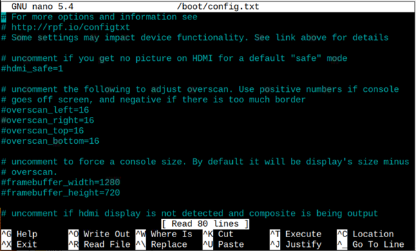
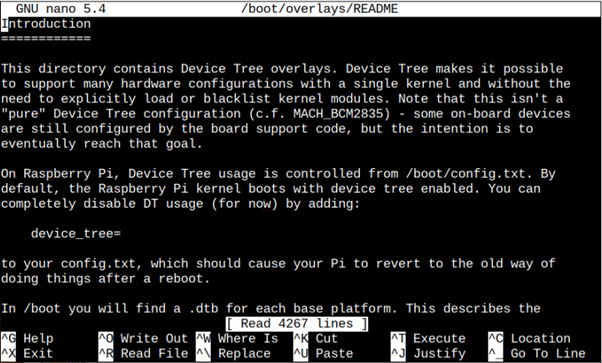
And then adding the entry “dtoverlay=uartx” within the file. Remember you must replace x in “uartx” with the UART number. In case of any confusion, you can get help by opening the Readme file using the following command:
Conclusion
You now gain sufficient knowledge about using Raspberry Pi 4 GPIO pins, but you need to be careful in making your projects on Raspberry Pi 4. A little mistake may burn your Raspberry Pi 4; thus, you have to follow the guidelines provided. Learning about the GPIO pins helps you to perform communication of your favourite Raspberry Pi 4 with other devices.