The Arduino Nano contains 14 digital input/output pins. Total of 8 analog pins are there. Arduino uses the 16 MHz clock generated using the crystal oscillator. To program Nano a USB mini connector is available. Like Arduino UNO it also has ICSP connector pins with an on board reset button. Using the Vin pin it can be powered up through the external power supply.
Setting Up Arduino Nano with Arduino IDE
To set up the Arduino Nano with the Arduino Integrated Development Environment (IDE) we need to install the required driver in the computer. Once the drivers are installed, we can program Arduino Nano using Arduino IDE after selecting the right port and board.
Here is a summary of steps needed to be followed:
- Install Arduino IDE on your computer. Download the latest IDE from the Arduino official site.
- Connect Nano board with PC through a USB mini cable.
- Open IDE select the Arduino Nano board and COM port that correspond to your Arduino Nano.
Once you have selected the correct board and port, you can test your setup by uploading a simple sketch (program) to your Arduino Nano. Go to “File” and select “Examples.” From the examples, select “Blink” and click “Upload.” This will cause the onboard LED on your Arduino Nano to blink, indicating that the sketch has been successfully uploaded.
Now we will cover all these steps in details.
Installing the Arduino Nano Drivers
First step before we can upload code in Arduino Nano, we need to install the required drivers.
Most Arduino Nano have onboard CH340 UART chips for serial communication. However, some Arduino Nano boards have CP2102 chips. You can read about both chips’ driver installation method separately in the mentioned articles:
Serial drivers are necessary for serial communication, without installation of drivers Arduino IDE cannot upload code to Arduino board and uploading failed exit status 1 error will appear.
Uploading LED Blinking Example
Once the drivers are installed, we can easily program Arduino Nano. Follow the steps to upload an LED blink program in Arduino Nano.
Step 1: Connect Arduino Nano with PC using mini-USB cable:

Step 2: Now open Arduino IDE and select the Arduino Nano board:

Step 3: Select the COM port at which Arduino Nano is connected:

Step 4: Select the Old Bootloader for Atmega328P. Go to: Tools>Processor>ATmega328P (Old Bootloader):
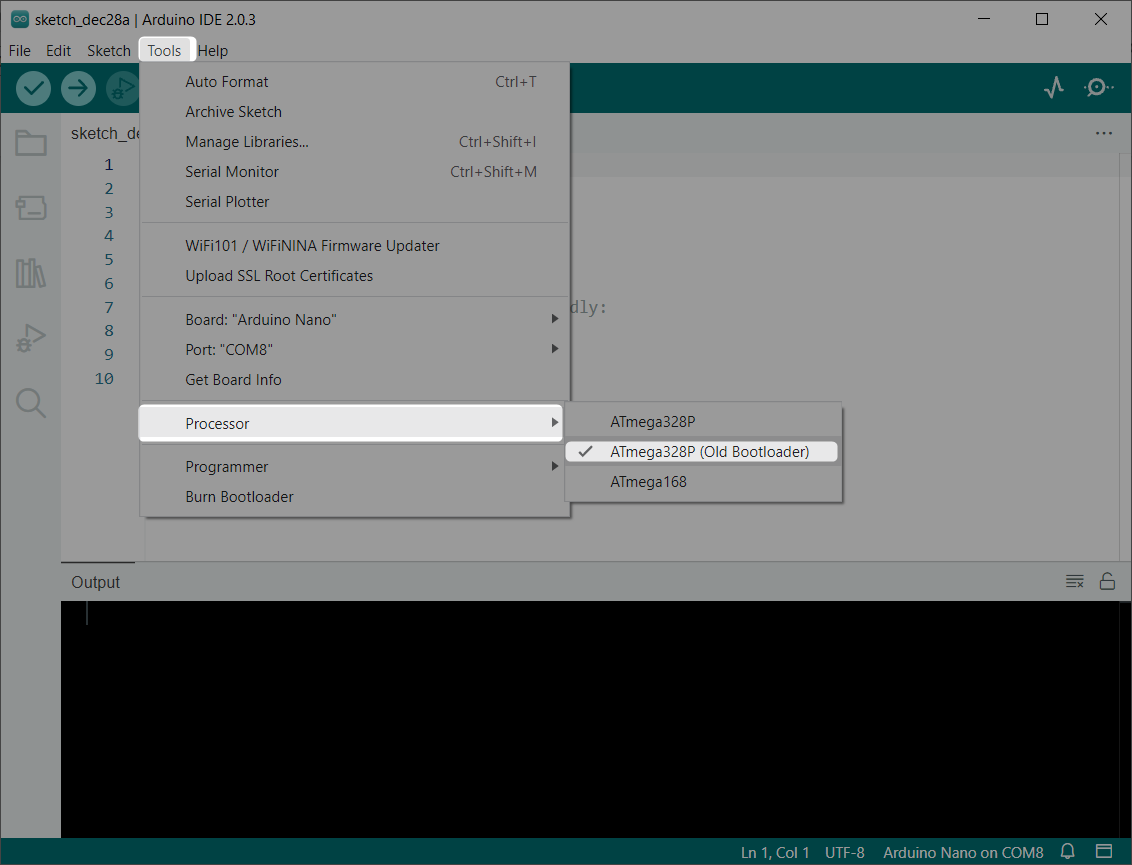
Now Arduino Nano is ready to upload LED blink programs in it.
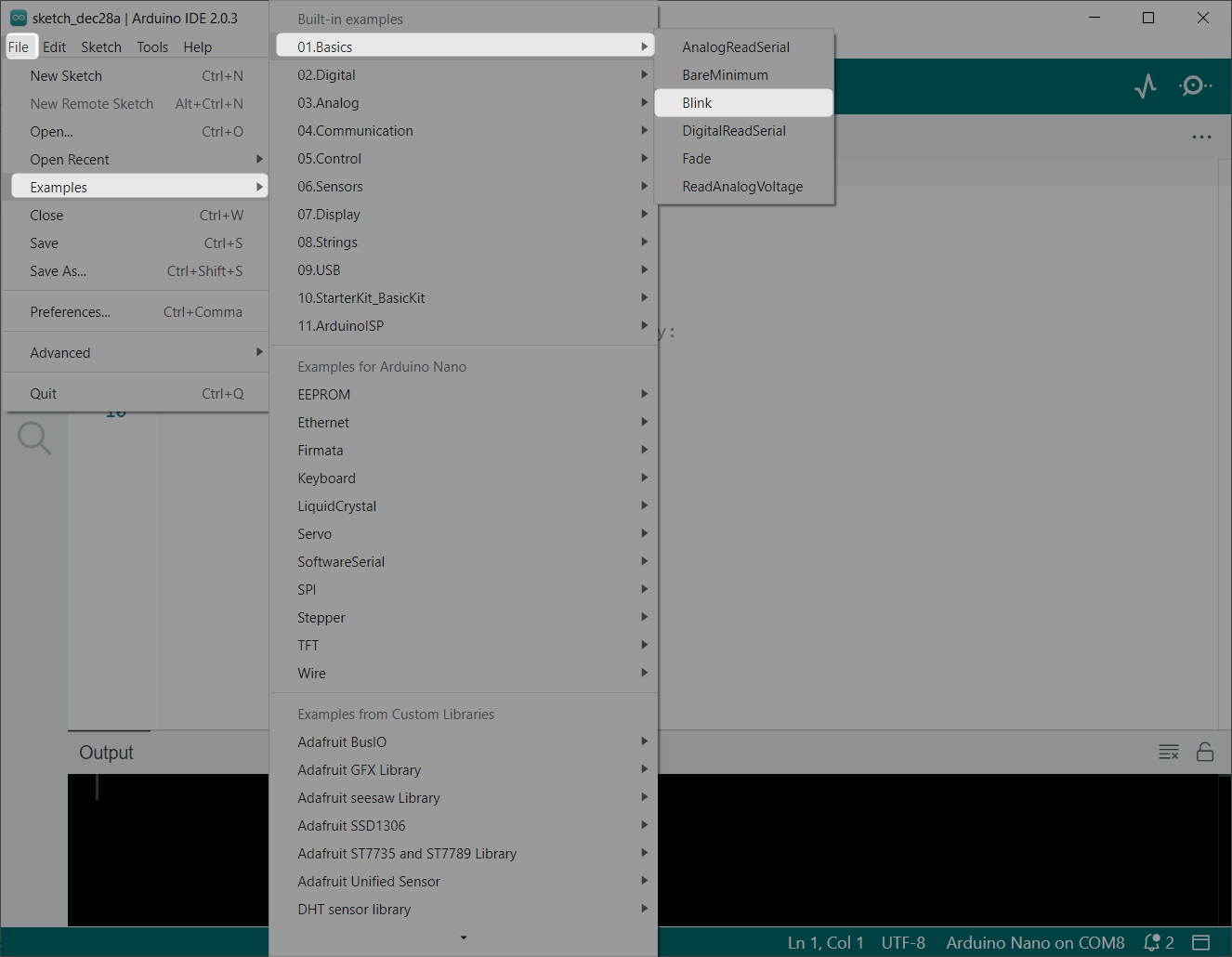
Step 5: Upload a LED blink sketch in Arduino Nano. Go to: Files>Examples>Basic>Blink:
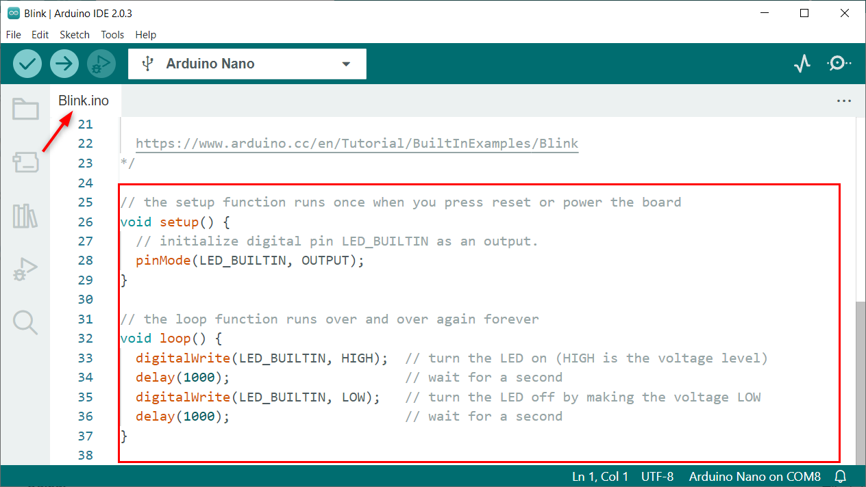
Step 6: A new window will open with an LED blink program:
Step 7: Upload code to Arduino Nano. Once code is uploaded successfully, we can see the Done Uploading message on screen:

Code
Following given code will blink the on-board built-in LED with a delay of 1 second:
pinMode(LED_BUILTIN, OUTPUT); //Built in LED defined as output
}
void loop() {
digitalWrite(LED_BUILTIN, HIGH); // LED ON by setting voltage HIGH
delay(1000); // delay of 1 sec
digitalWrite(LED_BUILTIN, LOW); // LED OFF by setting voltage LOW
delay(1000); // delay of 1 sec
}
Output
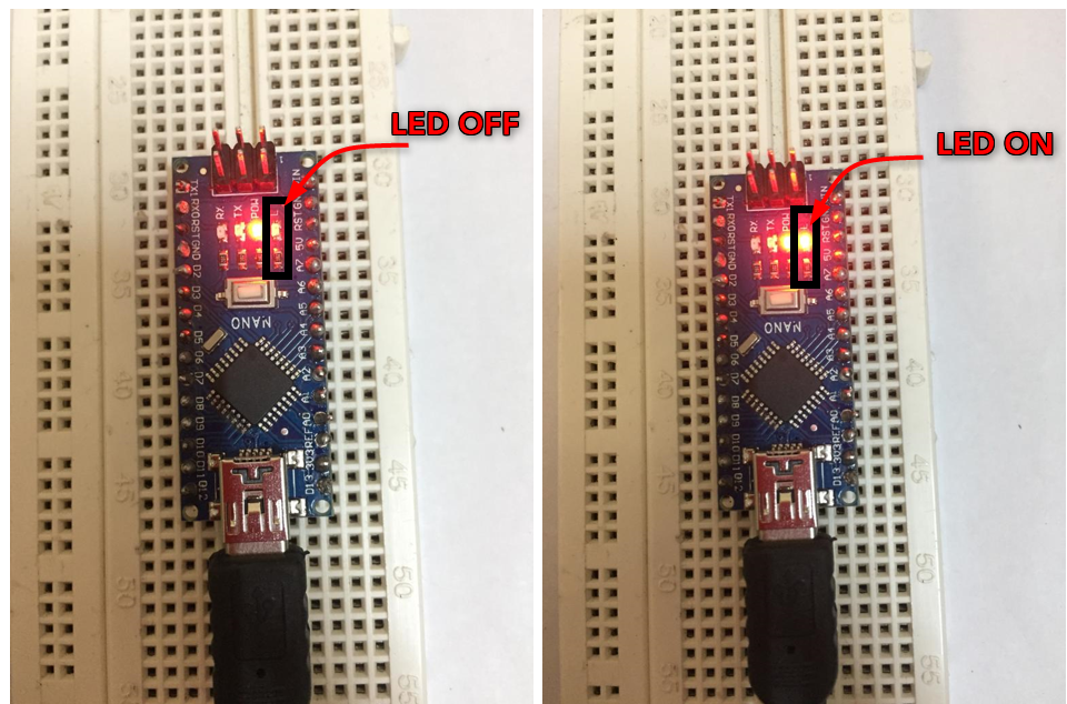
In the output we can see the onboard LED on the right side of the power LED is blinking with a delay of 1 second:
Blinking an External LED Using Arduino NANO
As we have covered the code for blinking the on-board LED. Now we will connect an LED at any digital pin of Arduino Nano and blink an external LED using the Arduino code.
Connect an external LED at pin 2 of Arduino Nano.
Code
After connecting the LED to the Nano board, upload the given code.
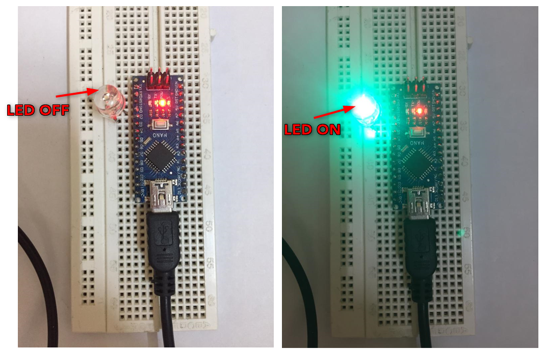
Below code will send a signal of HIGH and LOW alternatively with a delay of 2 seconds in between. For the first 2 seconds digital pin 2 will remain HIGH which will turn ON LED and for next 2 seconds digital pin 2 will remain in LOW state by setting the voltage level of pin to LOW so LED will remain OFF.
void setup() {
pinMode(LED_PIN,OUTPUT); /*LED PIN set as output*/
}
void loop()
{
digitalWrite(LED_PIN,HIGH); /*LED pin 2 set as HIGH*/
delay(2000); /*Delay of 2 sec*/
digitalWrite(LED_PIN,LOW); /*LED pin 2 is set as LOW*/
delay(2000); /*Delay of 2 sec*/
}
Output
After uploading code to Arduino Nano, we can see the output. LED connected externally at digital pin 2 will start blinking with a delay of 2 seconds.
Conclusion
Arduino Nano is a microcontroller board that is similar to Arduino UNO and uses the same ATmega328P microcontroller. This article covers all basic guidelines on how one can set up an Arduino Nano with an Arduino IDE and upload the LED blink program to the Nano board.