Fading a LED is an example to demonstrate the use of the analog output of PWM using Arduino. The PWM is also known as pulse width modulation is a technique in which we get analog output with varying pulse widths. We control the speed of switching by which we can convert the digital voltage wave into the analog voltage wave.
A better understanding of the PWM will be clear with the help of an example of fading a LED. In this write-up, the example of fading a LED is explained in detail with its hardware configuration.
What is the LED brightness control by PWM
Fading a LED means we will control the brightness of the LED using the digital input in which the brightness of the LED will be changed by the analog values.
We will make a simple circuit connecting a LED with Arduino and will control its brightness. The digital voltage which is in the range of 0-255 is converted to 0-5 volts, which means when the digital input will be 0 the output will be 0 volts when the digital input will be 127 the output will be 2.5 volts, and when the digital input will be 255 the output will be 5 volts.
In Arduino Uno, there are fourteen pins of digital I/O, pins 2,5,6,9,10, and 11 are dedicated to the PWM output. We will use any of these pins to get analog output.
How to make a LED fading in Arduino
To make a LED fading in Arduino, first, we have to make a circuit using the following components:
- Arduino Uno
- LED
- Resistor 500 ohms
- Connecting wires
We will ground the one leg of the LED, and to its other leg, we will connect a resistor. The open leg of the resistor will be connected to pin 3 which is a PWM output pin among the digital I/Os. The circuit diagram will be:
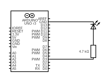
In the above circuit diagram, we have connected a cathode of the LED to the ground, the anode of the LED connected to the one terminal of the resistor and other terminals of a resistor are connected to the pin D3 of Arduino Uno.
For fading a LED, consider the code:
void setup() {
pinMode(ledpin, OUTPUT);
}
void loop(){
analogWrite(ledpin, bright);
bright=bright+fvalue;
if(bright==0 || bright==255){
fvalue=-fvalue ;
}
delay(50);
}
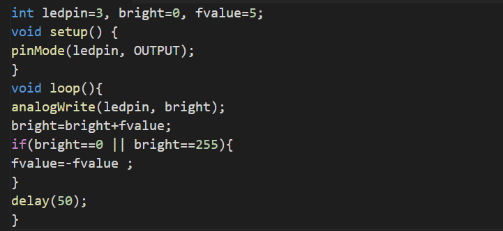
Explanation of code: In the code, we have declared three variables of integer data type; ledpin, bright, and fvalue. We have connected the led on pin D3 of Arduino so save the value 3 in it and fvalue is used to control the brightness of LED. Using the pinMode() function we define the behavior of the ledpin as output and in the loop section, we have written the value of bright to ledpin using the analogWrite() function. Then increase the brightness with fvalue and next, we applied the if condition to change or invert the cycle for example, if the value of bright reaches 255 from 0 then this condition will convert the value to -255 and it will start to minimize till it reaches to zero.
The simulation of this project is:

The hardware configuration of the circuit using the breadboard is:


Conclusion
In Arduino, fading a LED is one of the simplest examples to demonstrate the analogWrite() from the digital I/Os pins using the PWM technique. In this write-up, a simple circuit is made using an LED and a resistor. A code is written in Arduino IDE by which we control the brightness of a LED.