To get things clear, the ESP32’s internal Real-Time Clock (RTC) can keep track of time even when the main processor is powered off or in deep sleep. You can use the ESP32 RTC to keep track of time without using much power or affecting the main processor. But it still requires power to run, not that much but a minimum amount of power is required for internal RTC to run.
So with this, we are only left with the solution of using the external RTC module. Let’s check out the steps of interfacing the ESP32 board with the DS1307 RTC module.
Contents:
- What Is RTC DS1307 Module
- How to Interface RTC DS1307 and OLED Display with ESP32
- Finding the I2C Address of the OLED Display
- Interfacing the OLED and RTC DS1307 Module with ESP32
- Circuit Diagram
- Code
- Hardware
- Conclusion
1. What Is the RTC DS1307 Module
DS1307 is a low-power device that can keep track of time and date accurately. It uses binary-coded decimal (BCD) format. It can tell you time in a detailed format like seconds, minutes, and even hours and days. You can also print the date in full format like month and year. It also knows when it is a leap year, up to 2100. To communicate with DS1307, you can use the I2C protocol.
DS1307 has a built-in battery that can power it for about a year without an external 5V source. Using this battery backup, it can retain the time even when the main power is off. It also has 56 bytes of SRAM to store some data. The DS1307 is a handy device that has many applications when combined with an Arduino or ESP32 board. For example, this data can be helpful in data logging, alarm systems, or industrial control. If you need reliable timekeeping, the DS1307 is a great option.
RTC DS1307 Module Specifications
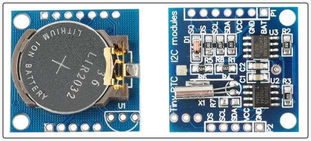
The RTC DS1307 module consists of the RTC IC, an EEPROM, a crystal oscillator, and a battery holder for backup.
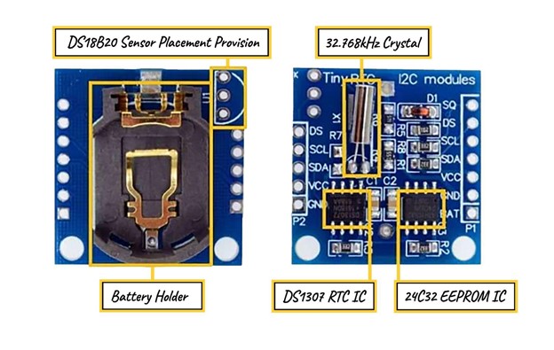
Below is the details of these parts:
DS1307 RTC IC: The DS1307 RTC IC is an 8-pin chip that keeps track of time and date using the I2C protocol. It uses very little power, less than 500nA. It can display time in seconds, minutes, and hours, and date in days, months, and years. It can also switch between 24-hour and 12-hour formats.
24C32 EEPROM IC: The 24C32 EEPROM IC is a 32-byte chip from Atmel that stores the settings, time, and date. It also uses the I2C protocol.
32.768kHz Crystal: The 32.768kHz crystal oscillator provides the clock frequency for the DS1307 RTC IC.
Battery Holder: The battery holder holds a CR2032 battery. It is a 3V lithium coin cell. It provides continuous power to the DS1307 RTC IC.
DS18B20 Sensor Provision: The DS18B20 sensor provision allows you to solder and use the DS18B20 temperature sensor. It is not pre-soldered. You can solder the through-hole package and get the temperature from the DS pin of the module.
The below list gives some quick specifications of the DS1307 RTC sensor:
- Operating voltage: 4.5–5.5 V, typically 5 V
- Current consumption: Less than 1.5 mA
- Accuracy: 0–40 °C, depends on the crystal
- Battery: CR2032 (3 V coin)
- Memory: 56 bytes of nonvolatile RAM
- Interface: Two-wire (I2C) serial interface
- Output: 1 Hz output pin
- Programmable square wave output: Consumes less than 500 nA in battery-backup mode
- Power-fail detection: Automatic power-fail detection and switch circuitry
- Power-sense circuit: It can auto switch to back up supply on power shortage
- Leap year compensation: Valid up to the year 2100
RTC DS1307 Module Pinout
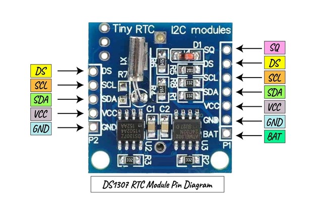
The module has several pins with different functions.
- VCC is the pin that needs a DC voltage between 3.3V and 5.5V to power the module.
- GND is the pin for low voltage or ground.
- SDA and SCL are the pins communicating data and clock signals through the I2C bus.
- DS is the pin that measures the temperature with the DS1307 sensor if you have one on the RTC module.
- SQ is the pin that generates a square-wave signal with a frequency of 1 Hz, 4 kHz, 8 kHz, or 32 kHz, depending on how you program it.
- BAT is the pin that uses a 3V battery to keep the time accurate when the main power is off.
2. How to Interface RTC DS1307 and OLED Display with ESP32
To interface ESP32 with DS1307 and OLED Display, you can use the built-in I2C pins of the ESP32 board. Both the DS1307 and OLED display are I2C-based devices. Then can communicate using the I2C master slave protocol over the I2C bus.
Before we move toward the interfacing of ESP32 with DS1307 and OLED display, first you have to install some required libraries.
Installing the Required Libraries
You are going to need two libraries, one for the RTC module and one for the OLED display. Using OLED with an RTC module, you can create amazing and interactive clock previews. If you have no plan of displaying the time on screen, then you can skip this library installation.
Following are the two libraries that you are going to need:
- RTClib (by Adafruit) is an Arduino IDE library to set and get time from an RTC. It also provides classes for manipulating dates, times, and durations. Using this library, you can interface and program the real-time clock (RTC) modules, such as DS1307 and DS3231.
- SSD1306 (by Adafruit) is a library for Arduino, using which you can interface and program the OLED displays with Arduino or any other microcontroller board.
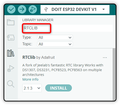
To download and install both these libraries in Arduino IDE, first open the Library Manager search for the RTClib library, and click Install:
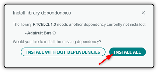
You will get the option to install only the library or its dependencies. Click the Install All button to completely install the library. This way you will not get any error if you modify the code which depends upon the dependencies of this library.
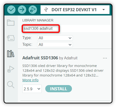
Similarly, search for the SSD1306 library. This library is needed for an OLED display. Click Install to proceed.
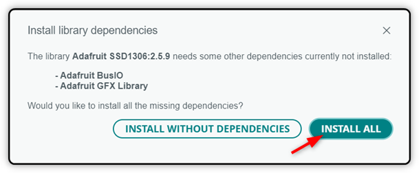
This time you will also get the same confirmation message. Click on the Install All option.
Now both the libraries for OLED and DS1307 are installed and ready to use. But before that, first, find out the I2C address for the OLED display.
3. Finding the I2C Address of OLED Display
The I2C address is a unique identifier for each device on the I2C bus. It allows the master device to communicate with a specific slave device by sending data to its address. The purpose of the I2C address is to avoid conflicts and confusion between multiple devices on the same bus.
To get the address of an I2C device, you can use a simple sketch that scans the bus and prints the addresses of the devices it finds. Alternatively, you can check the datasheet of the device to see its default or configurable address.
Here in our case after running the I2C scanner code the following I2C address of the OLED screen is displayed on the Arduino IDE terminal.
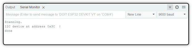
Most of the time, there is a high chance that you will also get the same 0x3C address for your OLED screen.
4. Interfacing the OLED and RTC DS1307 Module with ESP32
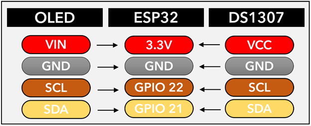
1. Connect the SDA and SCL pins of both the DS1307 module and the OLED display to the I2C pins of ESP32. Usually, these are GPIO 21 and GPIO 22, but you can assign any other pins also in the code if needed.
2. Connect both the VCC and GND of DS1307 and the OLED display to the 3.3V and GND pins of ESP32.
3. Insert a CR2032 coin cell battery into the DS1307 module to provide backup power for the real-time clock.
4. Upload the example code from this tutorial to your ESP32 board. Modify the code for custom outputs.
After uploading, a clock will start from the set time and display the time on the OLED screen.
5. Circuit Diagram
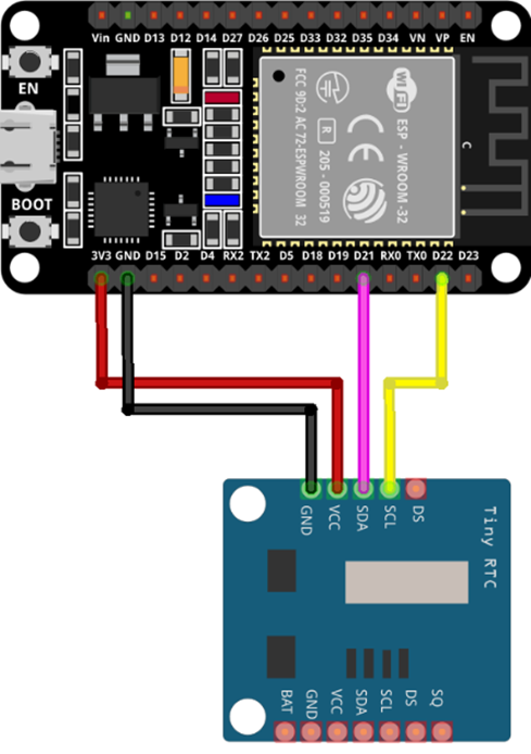
The circuit diagram of ESP32 with DS1307 is simple, with just four wires that need to be connected. You can shorten the I2C wires SDA and SCL of both the OLED and DS1307 sensors. Similarly, to power up both these sensors, the 3V3 and GND pin of the ESP32 board can be used. You can also power from a separate source if needed.
Note: It’s safe to power the RTC DS1307 from a 3.3V pin of ESP32 if the current limit of ESP32 is not exceeded. But if you want to be on a safe site you can either use a separate power source for the RTC module or try the low-power DS3231 sensor whose operating range is between 3.3 to 5.5 VDC.
The below image illustrates the connection of ESP32 with the RTC DS1307 sensor.
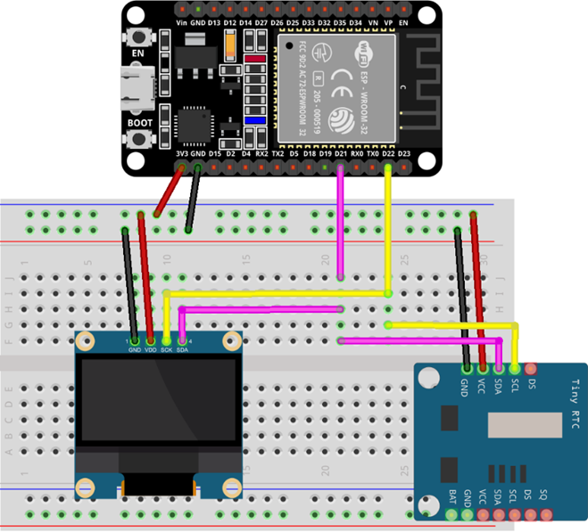
Similarly, if you want to connect the OLED screen to display the time, you can use the same I2C pins and the power pins of the ESP32 board.
6. Code
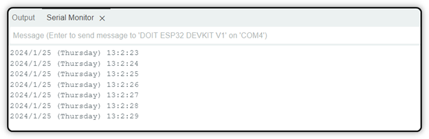
Using the code below, we will set the current date and time on the RTC. After setting the time, the code will display the time on the Arduino IDE terminal. Before you upload the code, you need to update it with your current date and time.
RTC_DS1307 DS1307_RTC;
char Week_days[7][12] = {"Sunday", "Monday", "Tuesday", "Wednesday", "Thursday", "Friday", "Saturday"};
void setup () {
Serial.begin(115200);
#ifndef ESP8266
while (!Serial);
#endif
if (!DS1307_RTC.begin()) {
Serial.println("Couldn't find RTC");
while(1);
}
DS1307_RTC.adjust(DateTime(F(__DATE__), F(__TIME__)));
}
void loop () {
DateTime now = DS1307_RTC.now();
Serial.print(now.year(), DEC);
Serial.print('/');
Serial.print(now.month(), DEC);
Serial.print('/');
Serial.print(now.day(), DEC);
Serial.print(" (");
Serial.print(Week_days[now.dayOfTheWeek()]);
Serial.print(") ");
Serial.print(now.hour(), DEC);
Serial.print(':');
Serial.print(now.minute(), DEC);
Serial.print(':');
Serial.print(now.second(), DEC);
Serial.println();
delay(1000);
}
This code uses the RTClib library to interface with a DS1307 real-time clock module that keeps track of the date and time.
The setup function started with initializing the baud rate. After that, inside this section, we defined the function to sync the date and time of the computer with the DS1307 sensor. This will upload the time of code compilation to the RTC sensor.
You can use the loop function to get the date and time from RTC. Then, you can display it on the serial monitor like this: year/month/day (day of the week) hour:minute:second. Remember to add a one-second delay after each loop, so the code doesn’t run too fast.
Display Current Time on OLED Display
To display the same time on the OLED screen, we have to add an extra code part for the OLED screen. Simply upload the given code. This code will display the current time on your OLED screen.
Remember, here we use the 0.96-inch 128×64 I2C SSD OLED Display Module. If you are using any other size, modify the code accordingly. Also, check the I2C address and modify it in the given code. In our case, we have an I2C address 0x3C for the OLED screen.
#include <Adafruit_GFX.h>
#include <Adafruit_SSD1306.h>
#include "RTClib.h"
#define SCREEN_WIDTH 128
#define SCREEN_HEIGHT 64
Adafruit_SSD1306 display(SCREEN_WIDTH, SCREEN_HEIGHT, &Wire, -1);
RTC_DS1307 RTC;
char days[7][12] = {"Sunday", "Monday", "Tuesday", "Wednesday", "Thursday", "Friday", "Saturday"};
void setup() {
Serial.begin(115200);
if (!RTC.begin()) {
Serial.println("Couldn't find RTC");
while (1);
}
RTC.adjust(DateTime(F(__DATE__), F(__TIME__)));
if (!display.begin(SSD1306_SWITCHCAPVCC, 0x3C)) {
Serial.println(F("SSD1306 allocation failed"));
for (;;);
}
delay(1000);
display.clearDisplay();
display.setTextSize(2);
display.setTextColor(WHITE);
display.setCursor(30, 20);
display.println("Linuxhint");
display.display();
delay(3000);
display.clearDisplay();
}
void loop() {
DateTime now = RTC.now();
display.clearDisplay();
display.setTextSize(2);
display.setCursor(0, 0);
display.print(now.day());
display.print('/');
display.print(now.month());
display.print('/');
display.print(now.year());
display.println(days[now.dayOfTheWeek()]);
display.println(' ');
display.setCursor(0, 40);
if (now.hour() < 10)
display.print('0');
display.print(now.hour());
display.print(':');
if (now.minute() < 10)
display.print('0');
display.print(now.minute());
display.print(':');
if (now.second() < 10)
display.print('0');
display.println(now.second());
display.display();
}
The code started with the libraries we installed for the RTC and the display. After that, it defines the screen size and the display address. It initializes the array with weekday names.
The setup part starts with serial communication. It checks if the RTC and the display are working or not. After that, we have defined a string text “Linuxhint” that will display for 3 seconds. This is an opening or startup message only, you can modify this message with your custom text also.
The loop function gets the DS1307 module date and time. After that, it clears the display and prints the date and time in a formatted way. The code also adds leading zeros to the hours, minutes, and seconds, in case their values are smaller than 10.
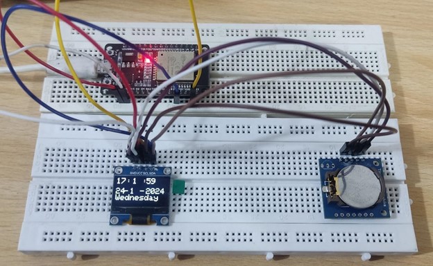
7. Hardware
After uploading the code to the ESP32 board, you will see the following output on the OLED screen. For hardware, we have used the OLED screen and an I2C RTC DS1307 module. ESP32 board with 30 pins is used. You can experiment with any other ESP32 board also, but make sure to connect the I2C pins correctly.
Conclusion
The RTC DS1307 has a 56-byte SRAM with battery backup support. It is an 8-pin device that uses an I2C communication protocol. To interface the DS1307 RTC module with the ESP32, you can use the I2C pins (GPIO 22 (SCL) and GPIO 21 (SDA)) of the ESP32 board. You can print the time on an Arduino IDE console or use any screen like OLED or I2C LCD to display the time. The DS1307 RTC module is a useful device for keeping track of time and date in various applications. Some main applications include data loggers, digital clocks, and smartwatches.