
ESP32-CAM
ESP32-CAM is a full-featured microcontroller that has a video camera as well. A micro-SD card is also integrated into it. It is smaller and can operate on low power. Not only that, but it is an advanced camera that can perform advanced functions such as image tracking and recognition.
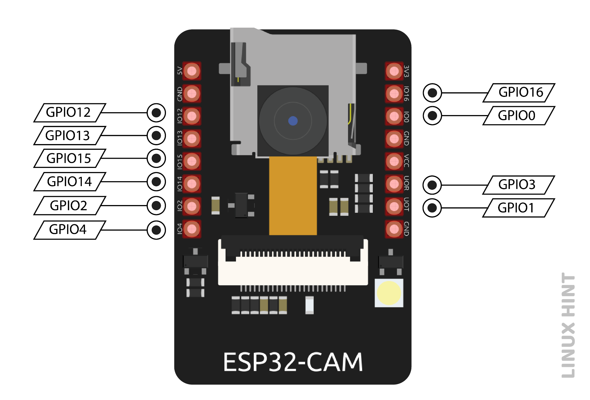
To understand the functioning of a microcontroller, it is necessary to understand its pinouts and connections before use. So, the pinout structure of the ESP32-CAM is as follows:
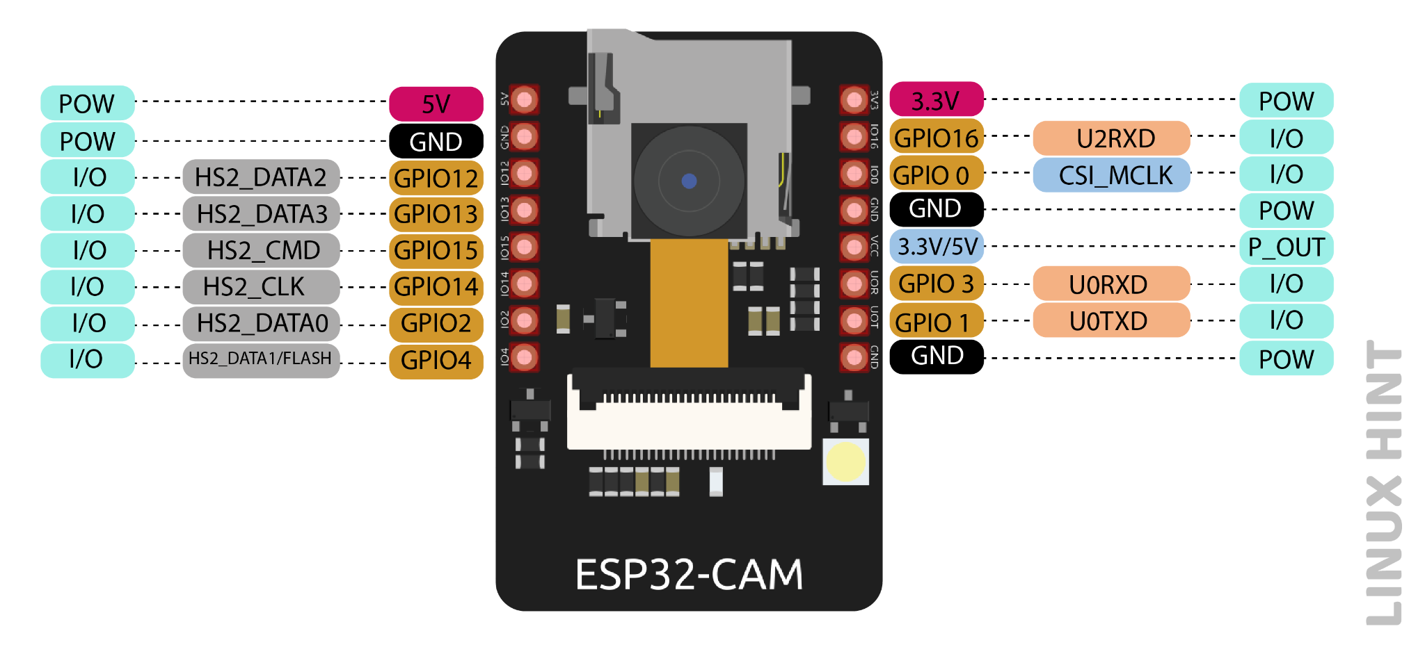
The ESP32-S chip has a total of 32 pins but many of them are internally used, so there are only 16 pins exposed to the pinout header which are available for ESP32-CAM.
Power Pins
ESP32-CAM has three ground pins (GND) and two power pins that are 3.3V and 5V. It is best advised to connect power to the 5V pin, as this provides efficient power for the operation of the camera.
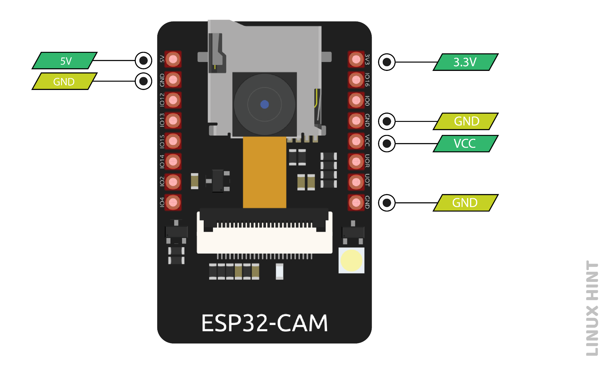
On the silkscreen, there is a pin labelled as VCC which is an output power pin. This is not a power pin for input, rather it is a power pin for output. By default, it gives the 3.3 V output whether it is connected with 3.3V or 5V input because it is soldered with the 3.3V pad. There is another 5V pad near the 3.3V pad. The 5V power can be made available on the VCC, by unsoldering the 3.3 V pad and making a jumper connection with the 5V pad.
GPIO Pins
Out of 32 total GPIO pins, there are only 10 GPIO pins available for ESP-32 CAM, as the rest of the pins are internally used for PSRAM and camera. By programming the proper registers these pins can be assigned with multiple peripheral duties such as touch, SPI, UART, and ADC.
GPIO 0 pin – Flash Mode Selection
GPIO 0 is a mode selection pin. When the GPIO0 is connected to the ground to make it low, it enables the flash mode. In flash mode, the code is flashed to the board. To disable the flash mode, the connection of this pin with the GND pin is removed. The microcontroller returns to the normal program execution mode.
GPIO 4 Pin
ESP-32 CAM has an inbuilt flash LED light. This is used to take pictures in the dark. This flashlight is connected to the GPIO4 pin. The GPIO 4 pin is also connected to the micro-SD card, so it needs to be programmed well when using both functions together.
GPIO 33 – Built-in Red LED
There is an LED red colour on the board near the reset button. When shining bright, it indicates that there is some operation going on.
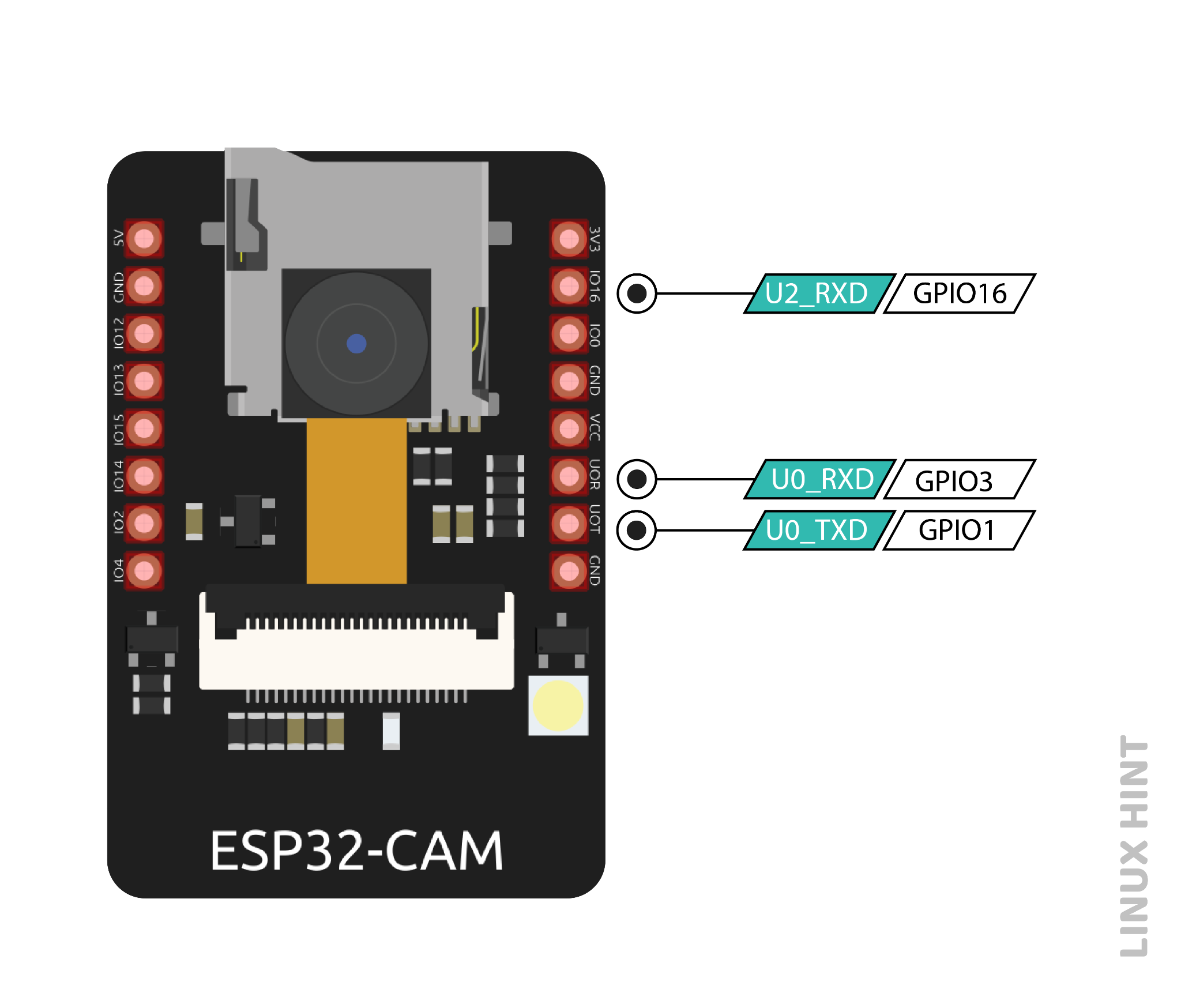
UART Pins
There are two interfaces of UART, UART0 AND UART2 on the ESP-32 S chip. The GPIO 1 (Tx), GPIO 3 (Rx), and GPIO 16 (Rx) are three serial pins. Serial pins are responsible for communication. The only pin of UART2 (GPIO 16) is broken out, so it doesn’t take part in communication and makes UART0 the only usable UART on the chip. ESP32 doesn’t have a built-in programmer, so the GPIO 1 pin is used to transmit and GPIO 3 is used to receive the data. These pins make communication connections and upload code to the board.
| GPIO1 | U0TXD (UART Transmission pin) |
| GPIO3 | U0RXD (UART Reception pin) |
| GPIO16 | U2RXD (UART2 Reception pin) |
Micro SD card pins
Following are the pins which are used to interface the SD card. All the microSD card pins are multipurpose, when the SD card is not in use, then these pins can be used as normal input/output pins.
| Micro SD card pins | ESP32 pins |
| CLK | GPIO 14 |
| CMD | GPIO 15 |
| DATA0 | GPIO 2 |
| DATA1 / flashlight | GPIO 4 |
| DATA2 | GPIO 12 |
| DATA3 | GPIO 13 |

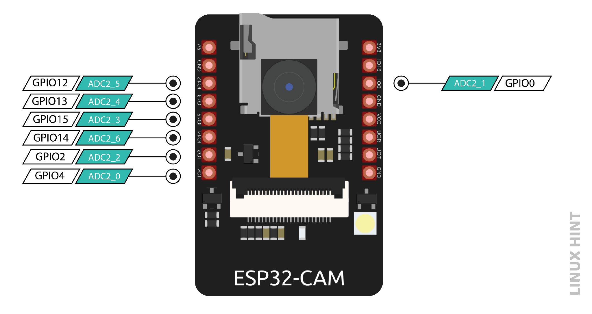
ADC pins
ADC (Analog to Digital converter) pins are capable of changing analog signal to digital signal. The ADC converts voltage into a bit which is understandable by the microprocessor. The ADC input channel has a 12-bit resolution, which means the readings can range from 0 to 4095, in which 0 will respond to 0V and 4095 will respond to 3.3V. ADC2 pins are internally used by the Wi-Fi driver, so they cannot be used when Wi-Fi is on. When Wi-Fi is on, there is trouble getting output from the ADC2 GPIO.
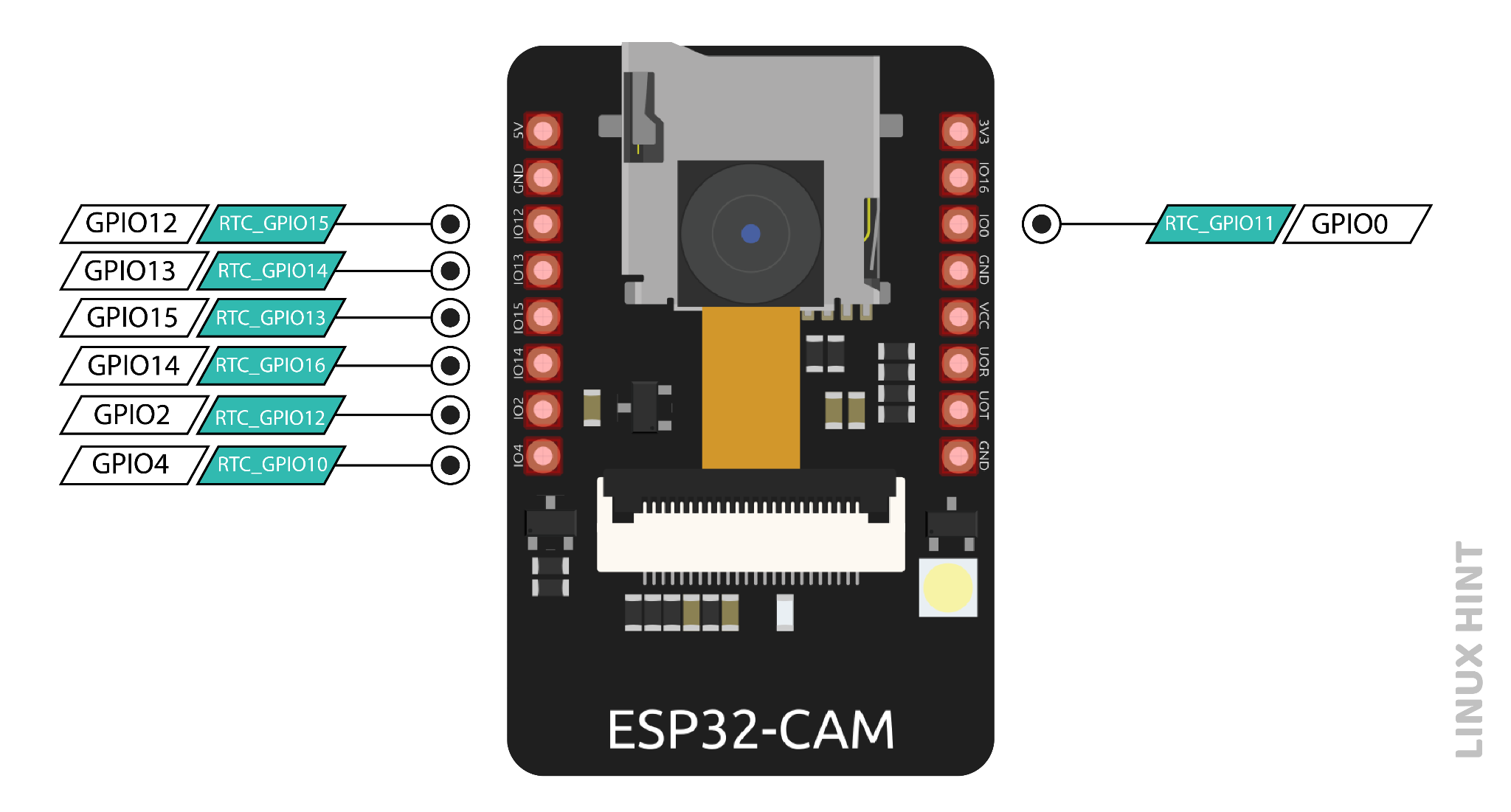
RTC GPIO Pins (Interrupt)
An external interrupt means an external interference in the normal functioning of the system. This interrupt can come from the user or any other device present among the networks. A common use of interrupts in ESP32-CAM is to wake up the microcontroller to perform a task. In ESP32-CAM, GPIO pins which are highlighted below can be configured as interrupts. These RTC GPIO pins are routed to the low-power subsystem; when an ultra-power coprocessor is running, these pins wake the ESP32 from sleep.
SPI pins
Serial Peripheral Interrupt (SPI) is a protocol for data communication that is used by a microcontroller to communicate with another or more than one external device and makes a bus-like connection. In SPI communication, there is a Master and a Slave. The master decides which operation to perform, and the slave accepts the command.
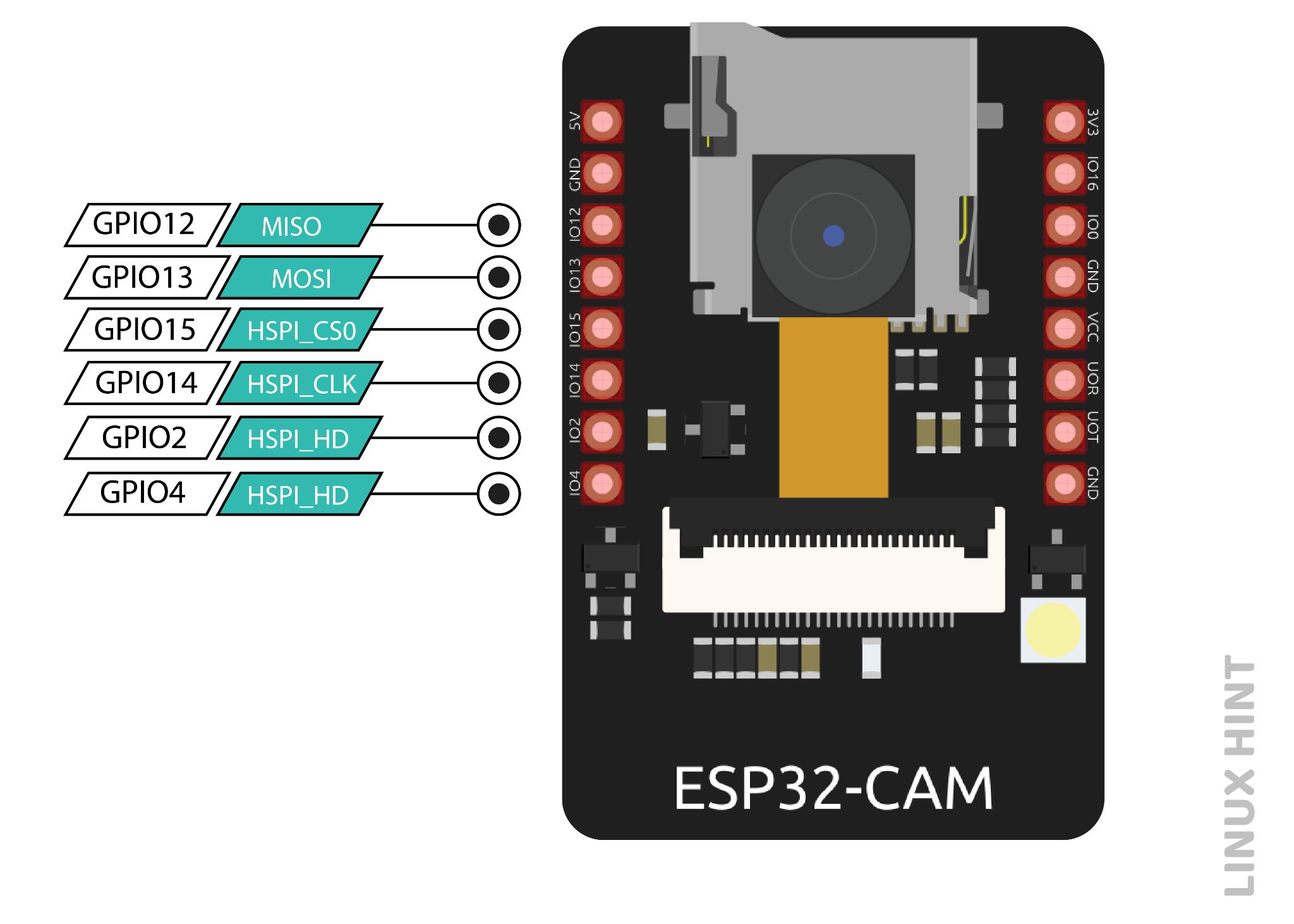
| SPI | HSPI |
| MOSI | GPIO 13 |
| MISO | GPIO 12 |
| CLK | GPIO 14 |
| CS | GPIO 15 |
MISO– This pin selects the line for sending data to the Master device.
MOSI- This pin carries out the selection of the master line to send data to the peripheral devices.
SCLK- To synchronise the transmission of data this pin selects the clock, which is generated by the master device.
SS- This pin is used to select the slave device.
Touch Pins
The ESP32-CAM has 7 internal capacitive touch sensing GPIOs, which can detect changes in anything that contains charge, such as human skin. When anything possessing charge comes to proximity, it can sense and detect variations in capacitance.
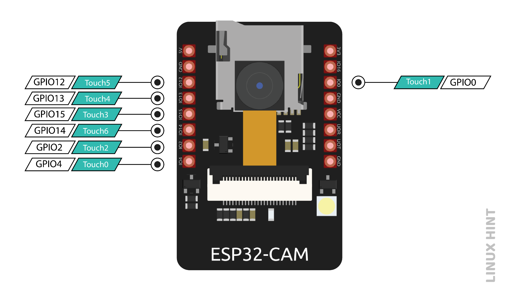
A capacitive touchpad can be made by attaching any conducting material to these pins, which can replace mechanical buttons.
PWM pins
All the 10 GPIOs can be used as PWM pins, and they are operated by a PWM controller.
The PWM controller has a PWM operator, a dedicated capture submodule, and PWM timers. The PWM timer generates timing in independent or synchronous form, the operator generates the waveform for the channel and the capture submodule captures events with external timing.
Conclusion
ESP32- CAM is a full-featured microcontroller that has vast applications in IoT. Its pinout configuration tells us that this board uses different communication protocols and is a great choice to use.