
We already did a tutorial on DS1307 interfacing with the ESP32 module. Today we will discuss the basics of the DS3231 RTC sensor and check how one can interface it with the ESP32 board.
Table of Contents:
2. How to Interface DS3231 With ESP32
6. How to Display the RTC DS3231 Time on an OLED Screen Using ESP32
1. What is the DS3231 RTC Module
The DS3231 module provides highly accurate timekeeping. It includes an integrated temperature-compensated crystal oscillator (TCXO) for giving us time with great precision. The module operates on the I2C protocol using the Master-Slave configuration. It can keep time and date with a backup battery even when there is no main input power. It is commonly used in devices that are time and date-dependent.
The DS3231 keeps tabs on seconds, minutes, and hours. It can also keep a record of dates and weekdays. When dealing with leap years, it automatically adjusts time accordingly. Also, it can display time in both 12-hour or 24-hour format, complete with an AM/PM indicator.
1.1. DS3231 Vs DS1307
Both DS3231 and DS1307 are time-keeping modules with battery backup support. However, the DS3231 is more accurate than the DS1307. The main reason is that DS1307 depends on external 32kHz crystal for timekeeping.
However, the RTC DS3231 features an internal Temperature Compensated Crystal Oscillator (TCXO). This makes it less affected by external temperature and as a result, it has an accuracy advantage of a few minutes per year than the DS1307.
1.2. DS3231 Pinout
DS3231 works using the I2C protocol. At the heart of this RTC module, we have the accurate RTC chip designed by Maxim. This chip handles all the time functions and communicates using the I2C with ESP32 or Arduino board.
The main pins of RTC DS3231 modules are:
- VCC: Connect this pin to the positive terminal of your power source.
- GND: Ground connection.
- SDA: Serial Data pin (used for I2C communication).
- SCL: Serial Clock pin (also part of the I2C interface).
- SQW: Square Wave output pin (can generate a periodic signal, e.g., for alarms or other timing purposes).
- 32K: 32KHz oscillator output (useful for precise timing applications).
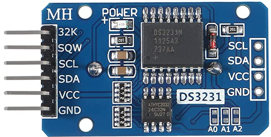
The following are the main onboard components of the RTC DS3231 module:
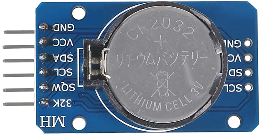
- Battery Holder: It allows the module to keep running when the external power is absent.
- RTC Chip: This chip maintains the time and date.
- AT24C32 EEPROM: It provides non-volatile storage for data logging and other purposes with 1,000,000 write cycles.
- TCXO: Temperature-compensated oscillator to provide the correct time for a varying range of temperatures.
- Temperature Sensor: It takes temperature readings and provides them as part of the module’s feature.
2. How to Interface DS3231 with ESP32
To interface DS3231 with ESP32, you need to install the RTClib library first. After installing this Adafruit RTC library, you can connect your ESP32 board with DS3231 using the I2C protocol. To connect ESP32 I2C with the RTC DS3231 module, you can use the ESP32 D21 and D22 pins.
2.1. Wiring Diagram of ESP32 with RTC DS3231
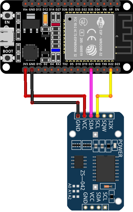
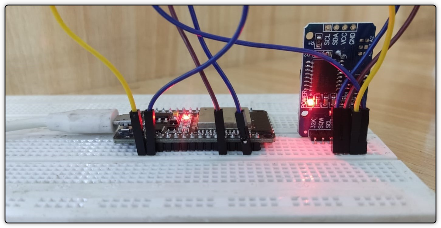
First, you have to wire the ESP32 with your I2C RTC DS3231 module. Follow the below-given pin configuration for wiring:
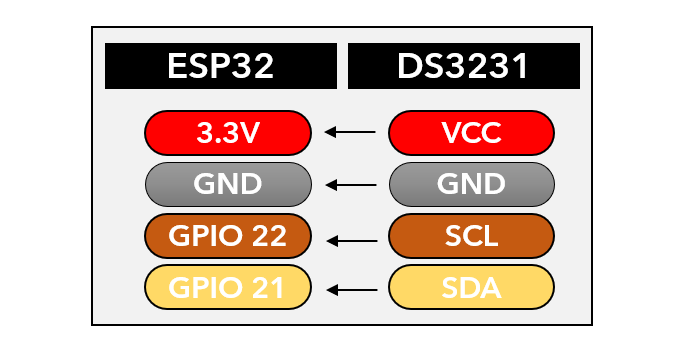
After connecting the ESP32 with RTC DS3231, your wiring diagram should look like this. You can also power the DS3231 from the VIN pin of ESP32. The operating voltages of DS3231 are 3.3 to 5.5 VDC.
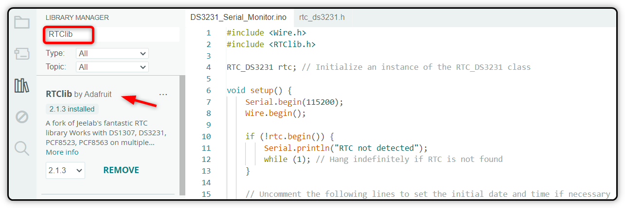
2.2. Installing the Required Libraries
Once the circuit is ready, the next step is to configure your ESP32 board with Arduino IDE. For interfacing DS3231, you will need to install the RTClib library. You can install it by using the Arduino IDE library manager.
3. Hardware
You will need the following hardware for designing the DS3231-based RTC clock with ESP32:
- ESP32 development board
- RTC DS3231 module
- CR2032 battery
- Jumper wires
- Breadboard
4. Code
After installing the RTC library, the next part is to write the code for DS3231 and upload it to the ESP32 board. First, you have to write the code to set your current time. After you set the time in DS3231, it will remember the time and keep on running even if your ESP32 board gets turned off.
Now open the Arduino IDE, compile, and burn the code to the ESP32 board.
#include <RTClib.h>
RTC_DS3231 rtc; // Initialize an instance of the RTC_DS3231 class
void setup() {
Serial.begin(115200);
Wire.begin();
if (!rtc.begin()) {
Serial.println("RTC not detected");
while (1); // Hang indefinitely if RTC is not found
}
//Uncomment the below line to set the initial date and time
//rtc.adjust(DateTime(__DATE__, __TIME__));
}
void loop() {
// Read current time from the sensor (DS3231)
DateTime now = rtc.now();
// Print the date and time on the same line with two digits for hours, minutes, and seconds
Serial.print("Current Date: ");
Serial.print(now.year(), DEC);
Serial.print("/");
printTwoDigits(now.month());
Serial.print("/");
printTwoDigits(now.day());
Serial.print(" Current Time: ");
printTwoDigits(now.hour());
Serial.print(":");
printTwoDigits(now.minute());
Serial.print(":");
printTwoDigits(now.second());
Serial.println();
delay(1000); // Update every 1 second
}
void printTwoDigits(int number) {
if (number < 10) {
Serial.print("0"); // Add a leading zero for single-digit numbers
}
Serial.print(number);
}
4.1. Code Explanation
The code starts by initializing the serial I2C communication with the help of a wire library. After that, we included the RTC library by Adafruit for interfacing with the DS3231 module. This library provides a function to interact with the RTC DS3231 module.
In the setup part, the I2C bus is started and checked for the available I2C devices. If not found, the program hangs indefinitely. The baud rate is also defined so you can check the output on the Arduino IDE serial monitor.
Setting the Clock for First Time
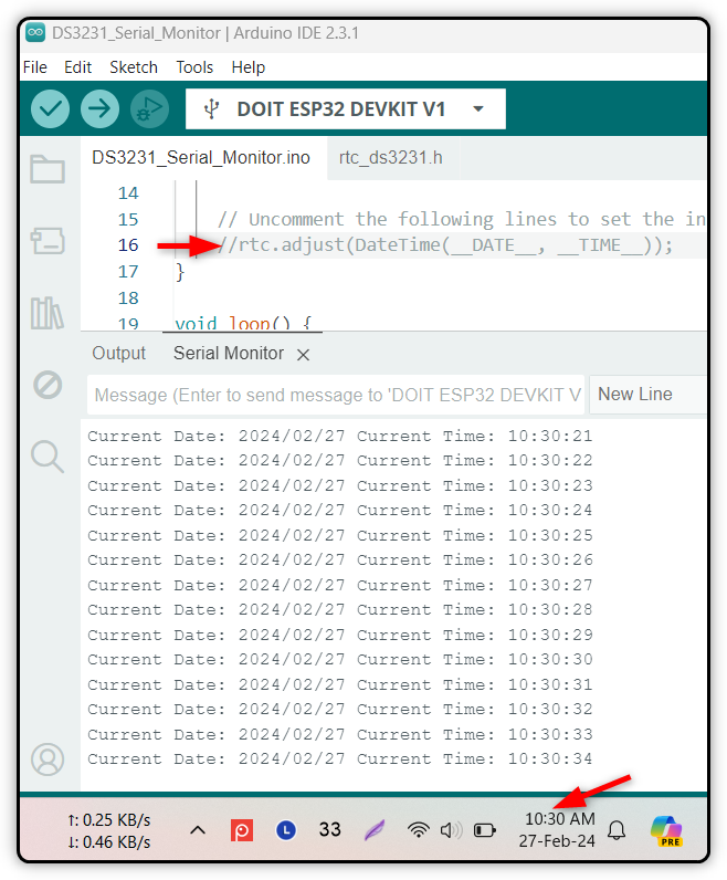
When programming the DS3231, you have to uncomment this line. This will get your system time and store it inside the RTC memory. By doing this, the RTC module clock gets synchronized with your system clock.

After the time is set you have to re-upload the above code but this time you have to comment the rtc.adjust() function line. Otherwise, this will overwrite your previous set time and when your ESP32 is powered off, the RTC will start again from the time you uploaded the code.
By doing this, your time will remain present in the RTC module background as long as the RTC module has power in its CR2032 cell.
In the loop part, the current date and time are read from the DS3231 module using the rtc.now() function. The date and time components are extracted and the formatted date is printed on the Arduino IDE serial monitor every one second.
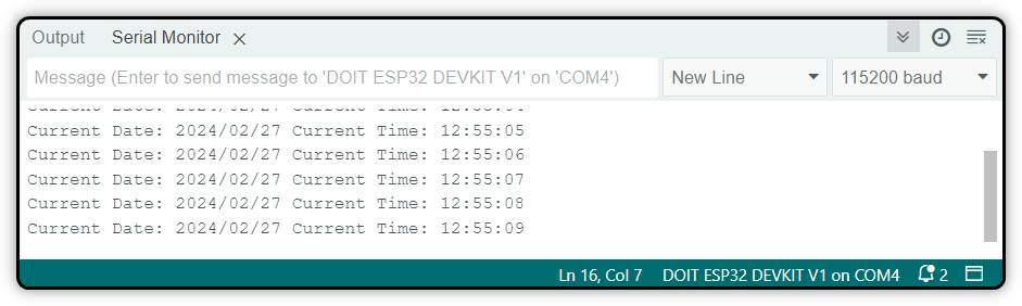
5. Output
After uploading the code to the ESP32 board, you will see the time will start printing on the Arduino IDE serial monitor.
6. How to Display the RTC DS3231 Time on OLED Screen Using ESP32
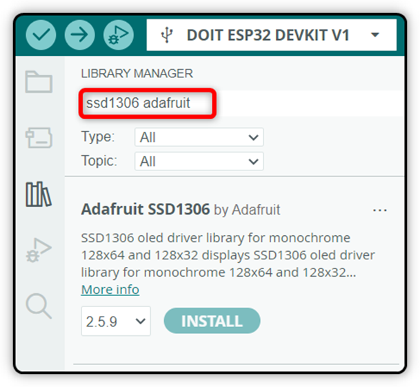
You can also go one step further and display the time on your OLED screen after reading it from DS3231. For this, you need to install the Adafruit GFX SSD1306 library in Arduino IDE.
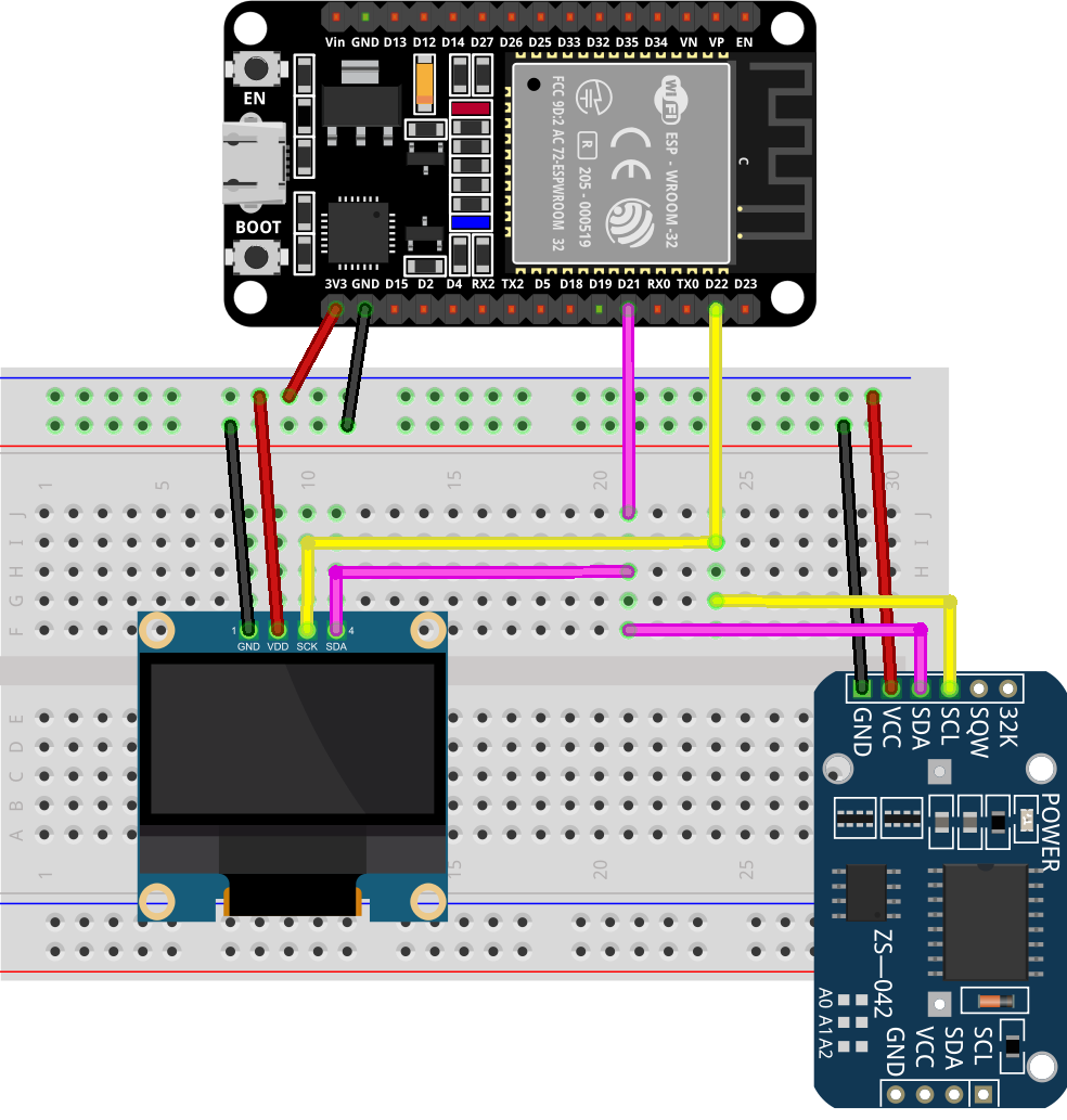
Once installed, connect the ESP32 with the OLED and RTC module in the following configuration.

After connecting your sensor, you will see the circuit look like the below schematic diagram.
Now upload the following DS3231 code to the ESP32 board.
#include <Adafruit_GFX.h>
#include <Adafruit_SSD1306.h>
#include "RTClib.h"
RTC_DS3231 rtc;
char days[7][12] = {"Sunday", "Monday", "Tuesday", "Wednesday", "Thursday", "Friday", "Saturday"};
Adafruit_SSD1306 display = Adafruit_SSD1306(128, 64, &Wire, -1);
void setup() {
Serial.begin(115200);
display.begin(SSD1306_SWITCHCAPVCC, 0x3C);
if (! rtc.begin()) {
Serial.println("Could not find RTC! Check circuit.");
while (1);
}
//uncomment the below line while setting time for the first time
//rtc.adjust(DateTime(__DATE__, __TIME__));
display.clearDisplay();
display.setTextColor(WHITE);
display.setTextSize(2);
display.setCursor(0, 20);
display.print("RTC CLOCK");
display.display();
delay(5000);
}
void loop() {
DateTime now = rtc.now();
display.clearDisplay();
display.setTextSize(2);
display.setCursor(75, 0);
display.println(now.second(), DEC);
display.setTextSize(2);
display.setCursor(25, 0);
display.println(":");
display.setTextSize(2);
display.setCursor(65, 0);
display.println(":");
display.setTextSize(2);
display.setCursor(40, 0);
display.println(now.minute(), DEC);
display.setTextSize(2);
display.setCursor(0, 0);
display.println(now.hour(), DEC);
display.setTextSize(2);
display.setCursor(0, 25);
display.println(now.day(), DEC);
display.print(days[now.dayOfTheWeek()]);
display.setTextSize(2);
display.setCursor(20, 25);
display.println("-");
display.setTextSize(2);
display.setCursor(35, 25);
display.println(now.month(), DEC);
display.setTextSize(2);
display.setCursor(60, 25);
display.println("-");
display.setTextSize(2);
display.setCursor(75, 25);
display.println(now.year(), DEC);
display.display();
}
Code Explanation
The code started with some important libraries that are required for RTC and OLED screens. The OLED display is set up using the Adafruit SSD1306 library.
In the loop part, the current date and time are obtained using the rtc.now(). After that, the OLED screen is cleared and the time components are displayed in a digital clock format. You can also modify the code to adjust the date and time format.
Once the code is uploaded to your board, you will get the current time on the OLED screen.

Note: The above code uses the 0x3C I2C address for OLED. This is the most common I2C address available on SSD1306 OLED displays. If you want to find the I2C address for your OLED screen, you can run the I2C Scanner code.
Conclusion
DS3231 is an RTC sensor that can be used for timekeeping. It has a battery backup that can keep time accurate even if your microcontroller board is turned off. To interface ESP2 with DS3231, you must install the RTClib library in your Arduino IDE. After that, you have to connect the RTC module over the I2C protocol using the digital pin of ESP32. Once connected, simply upload the code and adjust the time. Now the RTC sensor will keep time, and you can read it on your serial monitor on design time-based projects.