ESP32 is a microcontroller board that has a number of GPIO pins for several purposes. Each of these pins is designed for specific functions. ESP32 features a greater number of pins when compared to Arduino UNO or ESP8266 boards. To start working with ESP32 sufficient knowledge of its pin is essential. The goal of this guide is to discuss all the available pins on the board and their associated features.
This pinout guide to ESP32 contains the following content:
Before we move forward here, we summarized a brief introduction to the ESP32 IoT board.
1: Introduction to ESP32
-
- ESP32 is a very popular IoT-based microcontroller board.
- Main part of this microcontroller board is a Tensilica Xtensa LX6 chip designed by Espressif Systems.
- It contains a dual-core processor and each of these cores can be controlled separately.
- Total of 48 pins are present in the ESP32 chip however not all of these pins are exposed to users.
- ESP32 comes in two different versions: 30 pins and 36 pins.
- ESP32 can go up to a frequency starting from 80 MHz to 240 MHz.
- It contains a special ULP (Ultra Low Power Co-Processor) that saves a large amount of power using very less power while the main processor is OFF.
- It contains onboard WiFi and a dual Bluetooth module.
- ESP32 is cheaper than other microcontrollers.
1.1: ESP32 Pinout
Multiple variants of ESP32 are available in the market, today we will cover the detailed pinout of the 30 pin variant that comes with the ESP32-WROOM-32 microcontroller sometimes also referred to as WROOM32.
Total of 48 pins are available in ESP32 chips among which 30 pins are exposed to the user while others are integrated inside the microcontroller; some boards also contain six extra SPI flash integrated pins which sum up the total pin to 36.
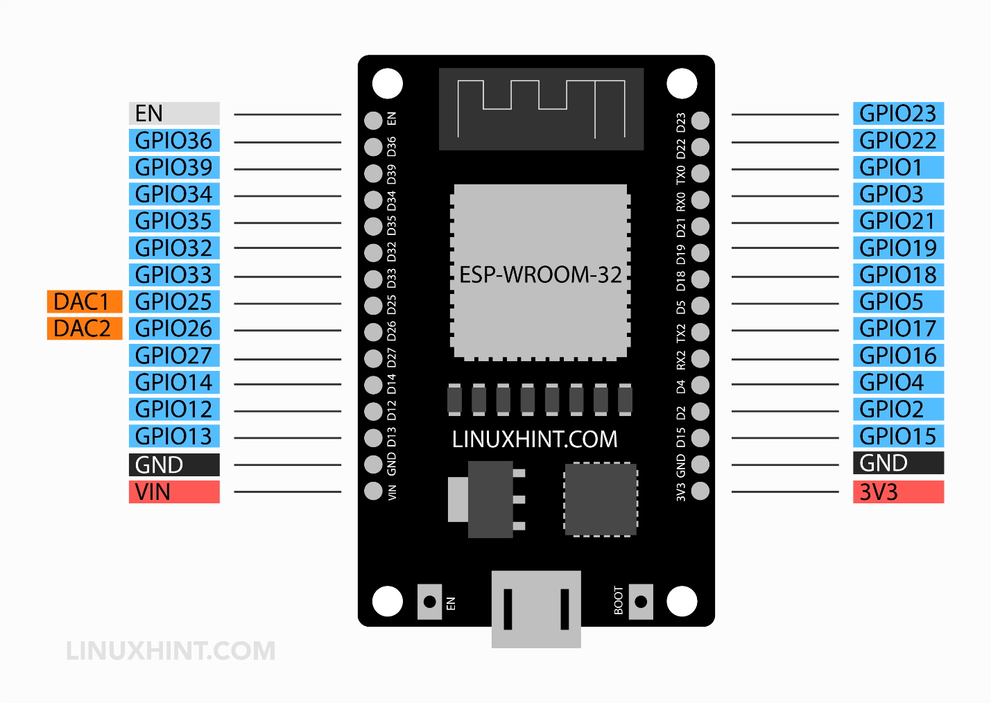
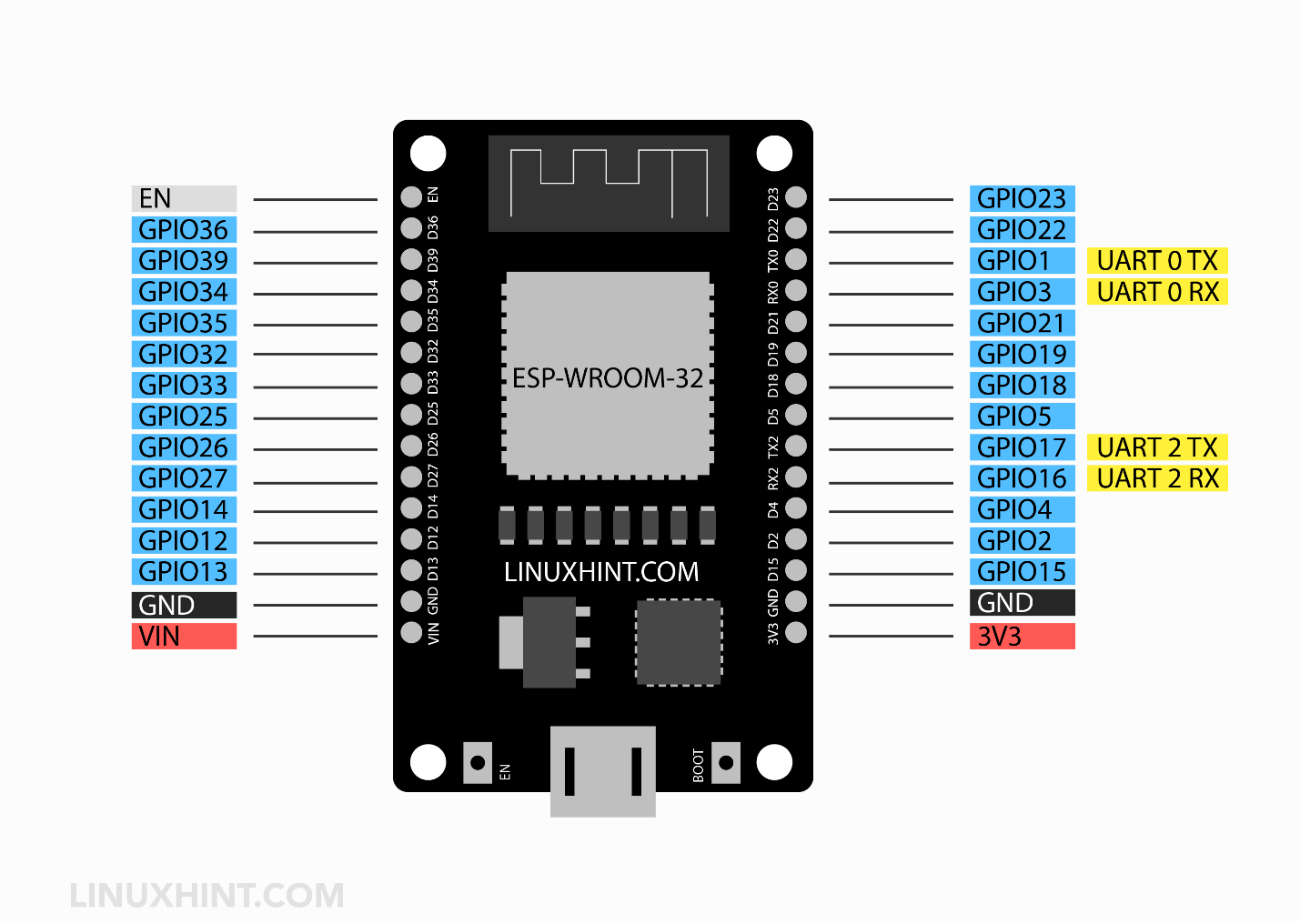
1.2: ESP32 30 Pin Version Board
The below image represents the detailed pinout of the ESP32 30 pin variant containing all its peripherals which we discuss one by one in detail.
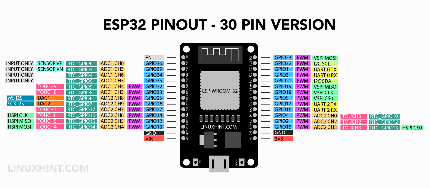
Some main peripherals inside ESP32 are:
-
- Total 48 pins*
- 18 12-bit ADC pins
- Two 8-bit DAC pins
- 16 PWM channel
- 10 Capacitive Touch Pins
- 3 UART
- 2 I2C
- 1 CAN
- 2 I2S
- 3SPI
*ESP32 chip contains a total of 48 pins out of which only 30 pins are available for external interfacing (in some boards 36 which include 6 extra SPI pins) remaining 18 pins are integrated inside the chip for communication purposes.
1.3: ESP32 36 Pin Version Board
Here is an image of an ESP32 board having a total of 36 pins.
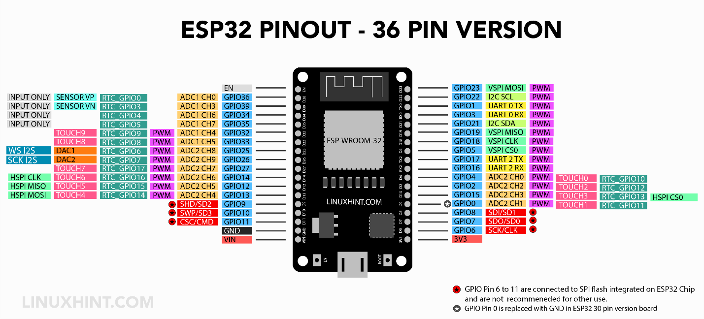
1.4: Difference between ESP32 30 Pin Version and ESP32 36 Pin Version
Both ESP32 boards share the same specification the only major difference here is 6 extra pins that are exposed in ESP32 (36 Pins) board are SPI flash integrated pins and secondly the GPIO 0 is replaced with a GND pin in ESP32 (30 Pins) board which results in missing of Touch 1 and ADC2 CH1 pin.

2: ESP32 GPIO Pins
As mentioned earlier ESP32 has a total of 48 pins out of which only 30 pins are accessible to users. Each of these 30 General purpose input output pins has a specific function and can be configured using a specific register. There are different GPIO pins like UART, PWM, ADC, and DAC.
Out of these 30 pins, some are power while some can be configured as both input and output while certain pins are input only.
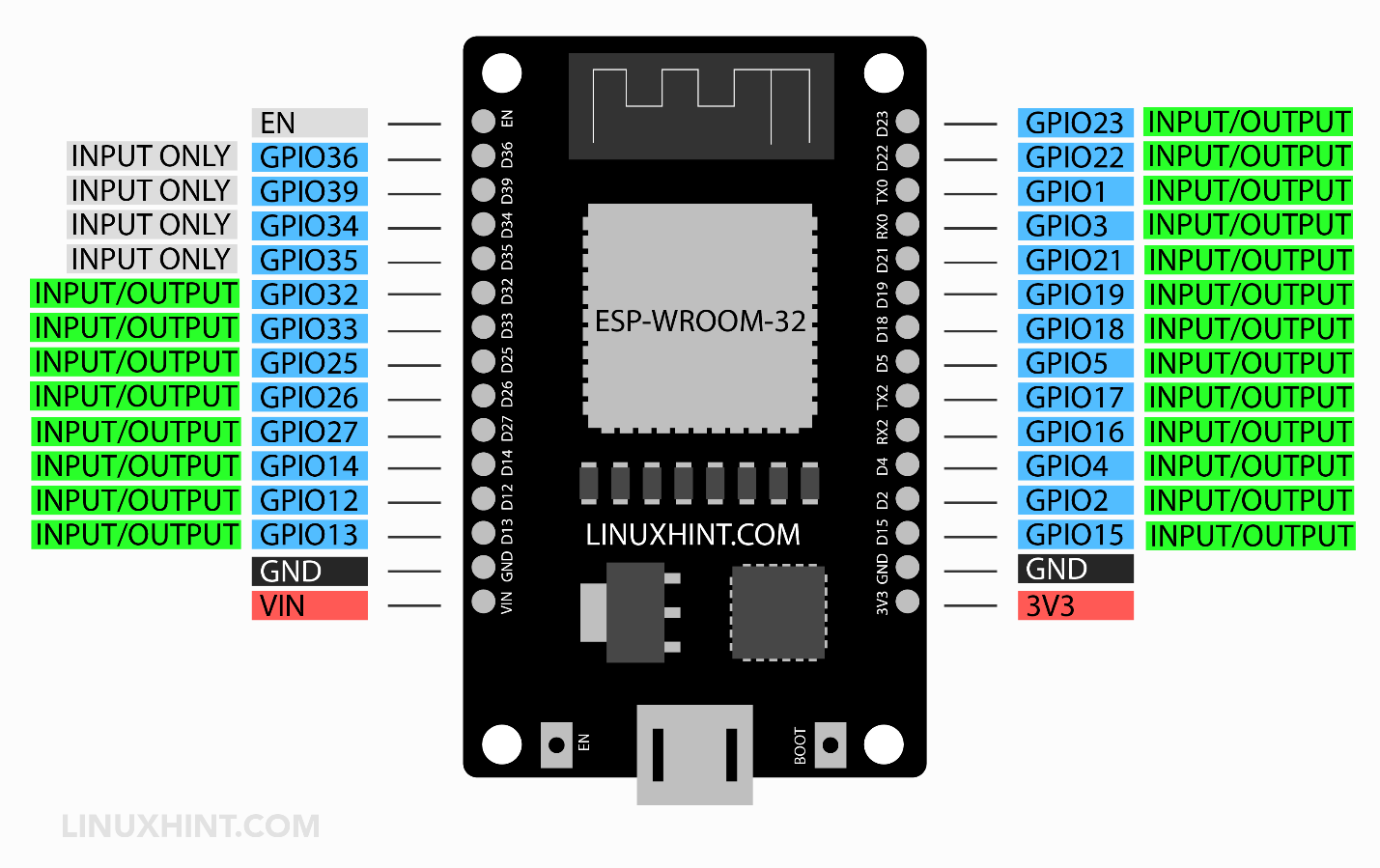
2.1: Input/Output Pins
Almost all GPIO pins can be configured as input and output except the 6 Serial peripheral interfaces (SPI) flash pins that cannot be configured for input or output purposes. These 6 SPI pins are available on the 36 pins version board.

The table given below explains the status of ESP32 GPIO pins that can be used as input and output:
Here OK means the corresponding pin can be used as input or output.
| GPIO PIN | INPUT | OUTPUT | Description |
| GPIO 0 | Pulled up | OK | PWM output at boot |
| GPIO 1 | Tx Pin | OK | Output debug at Boot |
| GPIO 2 | OK | OK | On board LED |
| GPIO 3 | OK | Rx Pin | High at Boot |
| GPIO 4 | OK | OK | – |
| GPIO 5 | OK | OK | PWM output at boot |
| GPIO 6 | – | – | SPI Flash Pin |
| GPIO 7 | – | – | SPI Flash Pin |
| GPIO 8 | – | – | SPI Flash Pin |
| GPIO 9 | – | – | SPI Flash Pin |
| GPIO 10 | – | – | SPI Flash Pin |
| GPIO 11 | – | – | SPI Flash Pin |
| GPIO 12 | OK | OK | Boot fail at High pull |
| GPIO 13 | OK | OK | – |
| GPIO 14 | OK | OK | PWM output at boot |
| GPIO 15 | OK | OK | PWM output at boot |
| GPIO 16 | OK | OK | – |
| GPIO 17 | OK | OK | – |
| GPIO 18 | OK | OK | – |
| GPIO 19 | OK | OK | – |
| GPIO 21 | OK | OK | – |
| GPIO 22 | OK | OK | – |
| GPIO 23 | OK | OK | – |
| GPIO 25 | OK | OK | – |
| GPIO 26 | OK | OK | – |
| GPIO 27 | OK | OK | – |
| GPIO 32 | OK | OK | – |
| GPIO 33 | OK | OK | – |
| GPIO 34 | OK | Input Only | |
| GPIO 35 | OK | Input Only | |
| GPIO 36 | OK | Input Only | |
| GPIO 39 | OK | Input Only |
2.2: Input Only Pins
GPIO pins 34 to 39 cannot be configured as output as these are only for input purposes. This is due to the lack of an internal pull-up or pull-down resistor hence can only be used as input.
Also, GPIO 36(VP) and GPIO 39(VN) are used for ultra-low noise preamplifiers in ESP32 ADC.
To summarize following are the input-only pins in ESP32:
-
- GPIO 34
- GPIO 35
- GPIO 36
- GPIO 39

2.3: Interrupt Pins
All GPIO pins in ESP32 can take external interrupts. This helps to monitor change at a specific interrupt instead of continuously monitoring.
2.4: RTC Pins
ESP32 also has some RTC GPIO pins. These RTC pins allow ESP32 to work in Deep Sleep mode. When ESP32 is inside the deep sleep mode while running an Ultra Low Power (ULP) co-processor these RTC pins can wake up ESP32 from deep sleep saving a large percentage of power.
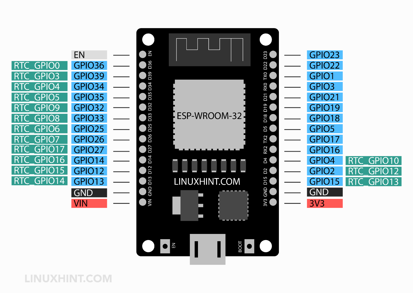
These RTC GPIO pins can act as an external excitation source to wake up ESP32 from a deep sleep at a particular time or interrupt. RTC GPIO pins include:
-
- RTC_GPIO0 (GPIO36)
- RTC_GPIO3 (GPIO39)
- RTC_GPIO4 (GPIO34)
- RTC_GPIO5 (GPIO35)
- RTC_GPIO6 (GPIO25)
- RTC_GPIO7 (GPIO26)
- RTC_GPIO8 (GPIO33)
- RTC_GPIO9 (GPIO32)
- RTC_GPIO10 (GPIO4)
- RTC_GPIO11 (GPIO0)
- RTC_GPIO12 (GPIO2)
- RTC_GPIO13 (GPIO15)
- RTC_GPIO14 (GPIO13)
- RTC_GPIO15 (GPIO12)
- RTC_GPIO16 GPIO14)
- RTC_GPIO17 (GPIO27)
3: ESP32 ADC Pins
The ESP32 board has two integrated 12-bit ADCs also known as SAR (Successive Approximation Registers) ADCs. The ESP32 board ADCs support 18 different analog input channels which means we can connect 18 different analog sensors to take input from them.
But this is not the case here; these analog channels are divided into two categories channel 1 and channel 2, both these channels have some pins that are not always available for ADC input. Let’s see what those ADC pins are along with others.
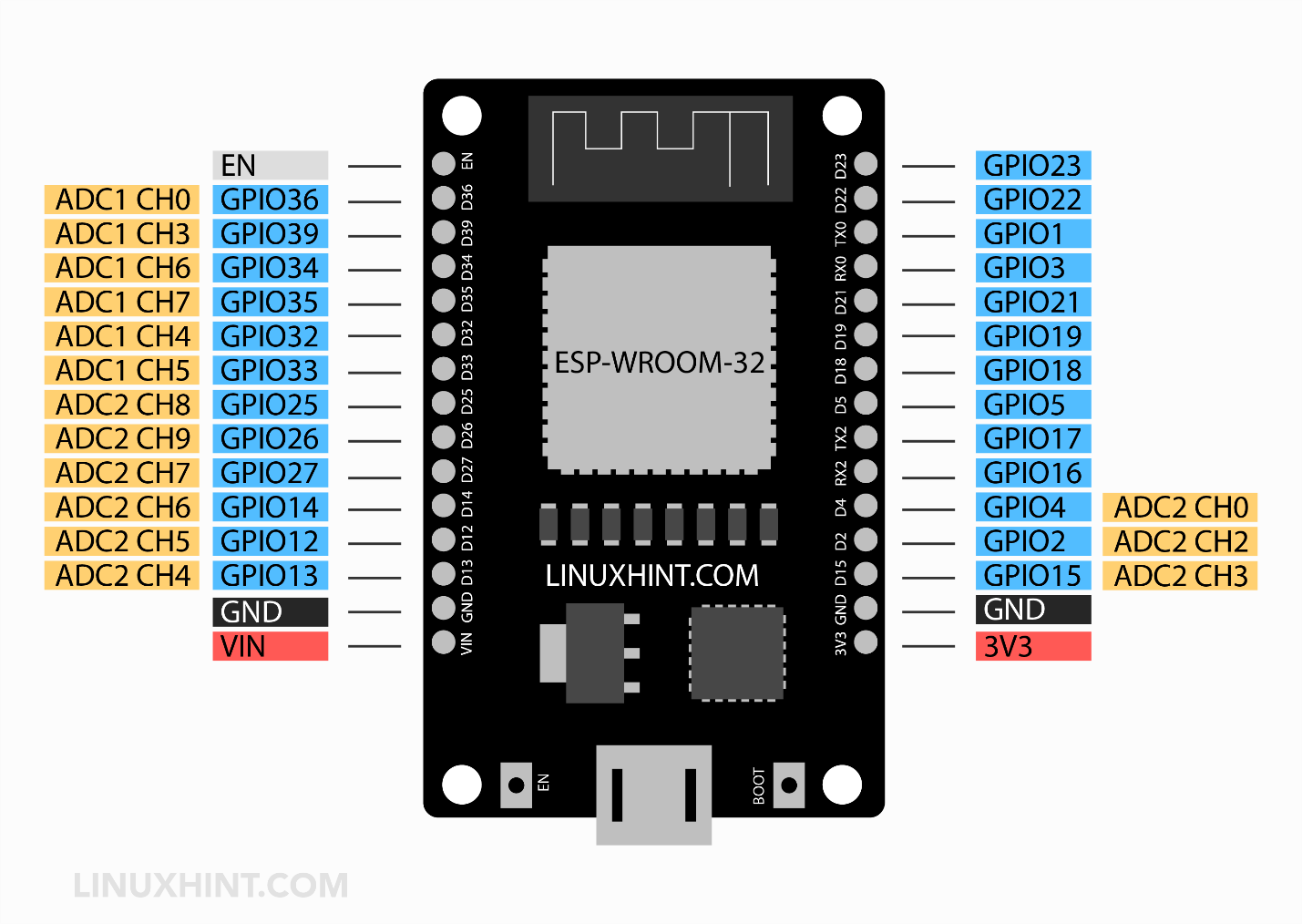
3.1: ESP32 ADC Pinout
As mentioned earlier the ESP32 board has 18 ADC channels. Out of 18, only 15 are available in the DEVKIT V1 DOIT board having a total of 30 GPIOs.
Take a look at your board and identify the ADC pins as we highlighted them in the image below:
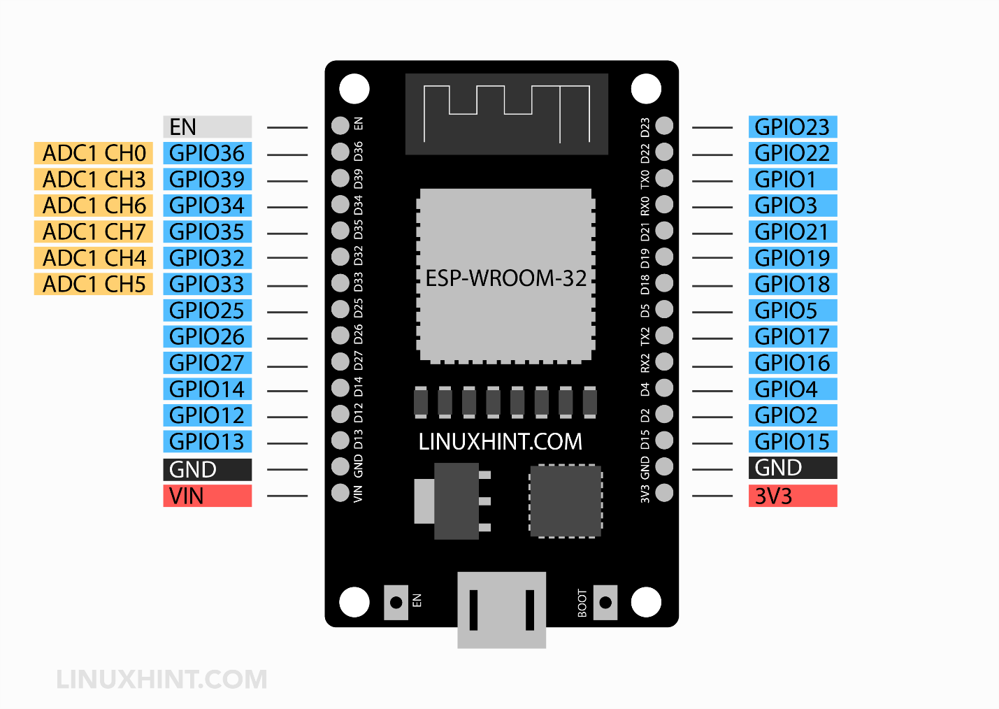
3.2: Channel 1 ADC Pin
Following is the given pin mapping of the ESP32 DEVKIT DOIT board. ADC1 in ESP32 has 8 channels however the DOIT DEVKIT board only supports 6 channels. But I guarantee these are still more than enough.
| ADC1 | GPIO PIN ESP32 |
| CH0 | 36 |
| CH1 | 37* (NA) |
| CH2 | 38* (NA) |
| CH3 | 39 |
| CH4 | 32 |
| CH5 | 33 |
| CH6 | 34 |
| CH7 | 35 |
*These pins are not available for external interfacing; these are integrated inside ESP32 chips.
The following image shows ESP32 ADC1 channels:
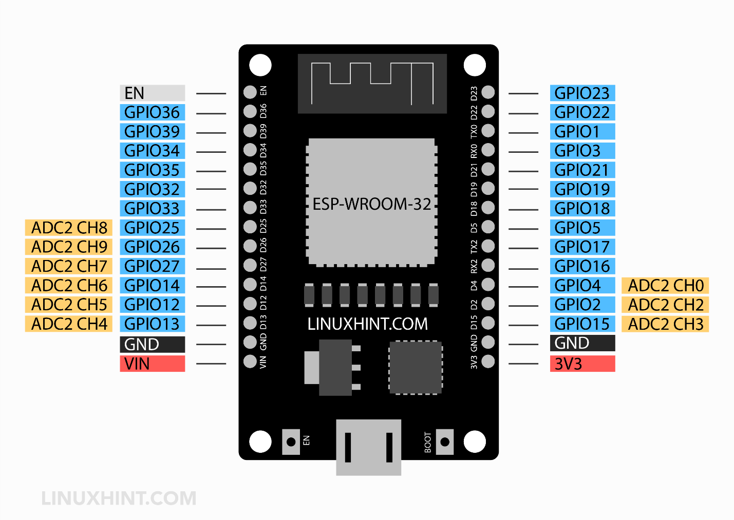
3.3: Channel 2 ADC Pin
DEVKIT DOIT boards have 10 analog channels in ADC2. Although ADC2 has 10 analog channels to read analog data, these channels are not always available to use. ADC2 is shared with onboard WiFi drivers, which means at the time the board is using WIFI these ADC2 will not be available. The solution to this problem is to use ADC2 only when the Wi-Fi driver is off.
| ADC2 | GPIO PIN ESP32 |
| CH0 | 4 |
| CH1 | 0 (NA in 30 pin version ESP32-Devkit DOIT) |
| CH2 | 2 |
| CH3 | 15 |
| CH4 | 13 |
| CH5 | 12 |
| CH6 | 14 |
| CH7 | 27 |
| CH8 | 25 |
| CH9 | 26 |
Below given image shows the pin mapping of the ADC2 channel.
3.4: How to Use ESP32 ADC
ESP32 ADC works similarly to Arduino only difference here is it has 12-bit ADC. So, the ESP32 board maps the analog voltage values ranging from 0 to 4095 in digital discrete values.

-
- If the voltage given to ESP32 ADC is zero in an ADC channel the digital value will be zero.
- If the voltage given to ADC is maximum means 3.3V the output digital value will be equal to 4095.
- To measure higher voltage, we can use the voltage divider method.
Note: ESP32 ADC is by default set at 12-bits, however, it’s possible to configure it into 0-bit,10-bit, and 11-bit. The 12-bit default ADC can measure value 2^12=4096 and the analog voltage ranges from 0V to 3.3V.
3.5: ADC Limitation on ESP32
Here are some limitations of ESP32 ADC:
-
- ESP32 ADC cannot directly measure voltage greater than 3.3V.
- When Wi-Fi drivers are enabled ADC2 cannot be used. Only 8 channels of ADC1 can be used.
- The ESP32 ADC is not very linear; it shows non-linearity behavior and cannot distinguish between 3.2V and 3.3V. However, it is possible to calibrate ESP32 ADC. Here is an article that will guide you to calibrate ESP32 ADC nonlinearity behavior.
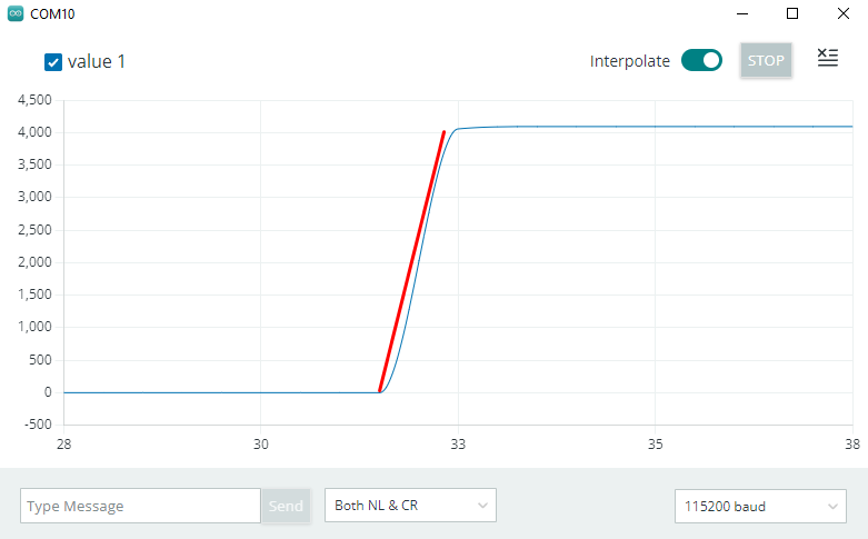
The nonlinearity behavior of ESP32 can be seen on the serial monitor of Arduino IDE.
4: DAC Pins
ESP32 features two onboard 8-bit DAC (Digital to Analog converter). Using ESP32 DAC pins any digital signal can be transformed into analog. DAC pins application includes voltage and PWM control.
Following are the two DAC pins in the ESP32 board.
-
- DAC_1 (GPIO25)
- DAC_2 (GPIO26)
5: PWM Pins
The ESP32 board contains 16 independent pulse width modulation (PWM) channels that can output different PWM signals. Almost all GPIOs can generate a PWM signal however the input-only pins 34,35,36,39 cannot be used as PWM pins as they cannot output a signal.
Note: In 36 pin ESP32, onboard 6 SPI flash integrated pins (GPIO 6, 7, 8, 9, 10, 11) cannot be used as PWM.

Read here for a complete beginner’s guide for controlling ESP32 PWM pins using Arduino IDE.
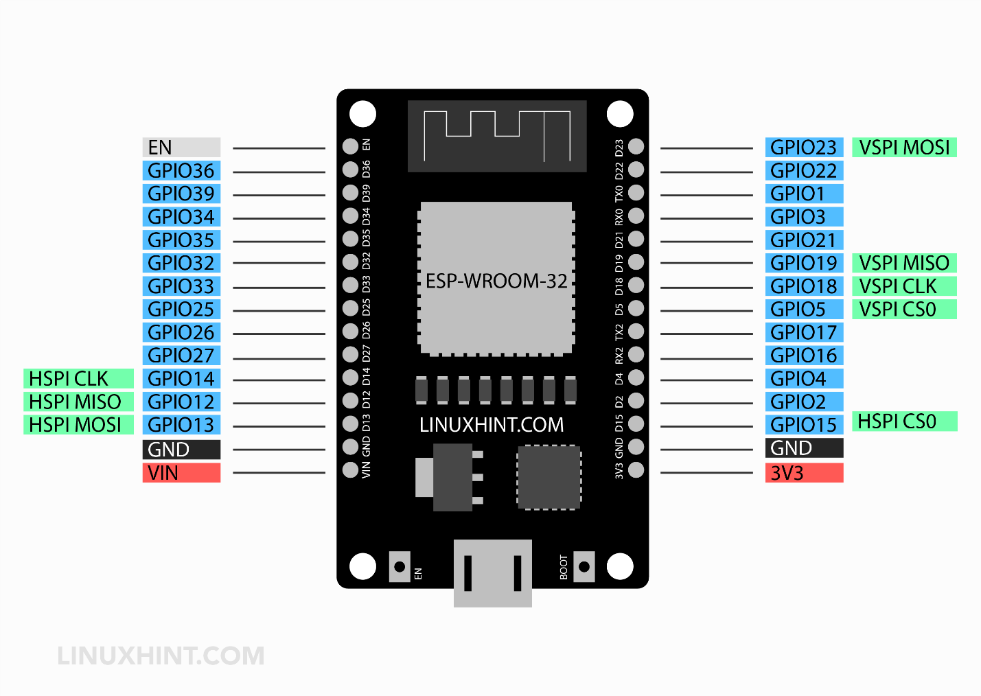
6: SPI Pins in ESP32
ESP32 has four SPI peripherals integrated into its microcontroller:
-
- SPI0: Cannot be used externally only for internal communication
- SPI1: Cannot be used externally with SPI devices. Only for internal memory communication
- SPI2: SPI2 or HSPI can communicate with external devices and sensors. It has independent bus signals with each bus ability to control 3 slave devices.
- SPI3: SPI3 or VSPI can communicate with external devices and sensors. It has independent bus signals with each bus ability to control 3 slave devices.
Most ESP32 boards come with preassigned SPI pins for both the SPI2 and SPI3. However, if not assigned we can always assign SPI pins in code. Following are the SPI pins found in most of the ESP32 boards which are preassigned:
| SPI Interface | MOSI | MISO | SCLK | CS |
| VSPI | GPIO 23 | GPIO 19 | GPIO 18 | GPIO 5 |
| HSPI | GPIO 13 | GPIO 12 | GPIO 14 | GPIO 15 |
Above mentioned SPI pins can vary depending on the board type. Now we will write a code to check ESP32 SPI pins using Arduino IDE.
For a complete tutorial on Serial Peripheral Interface click here.
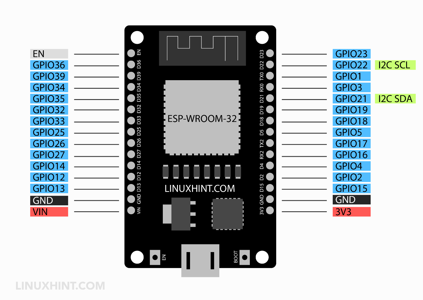
7: I2C Pins
ESP32 board comes with a single I2C bus that supports up to 120 I2C devices. By default, two SPI pins for SDA and SCL are defined at GPIO 21 and 22 respectively. However, using the command wire.begin(SDA, SCL) we can configure any GPIO as an I2C interface.
The following two GPIO pins are by default set for I2C:
-
- GPIO21 – SDA (Data pin)
- GPIO22 – SCL (Clock Synchronization pin)
8: I2S Pins
I2S (Inter-IC Sound) is a synchronous communication protocol that transmits audio signals between two digital audio devices serially.
ESP32 has two I2S peripherals, and each of them operates in half duplex communication mode. However, we can also combine them to operate in full duplex mode.
Normally the two DAC pins in ESP32 are used for I2S audio communication. Following are the I2S pins in ESP32:
-
- GPIO 26 – Serial Clock (SCK)
- GPIO 25 – Word Select (WS)
For I2S Serial Data (SD) pins we can configure any GPIO pin.

For more detailed documentation on ESP32 I2S communication protocol visit Espressif System ESP32 official I2S Documentation.
9: UART
By default, ESP32 has three UART interfaces that are UART0, UART1, and UART2. Both UART0 and UART2 are externally usable however the UART1 is not available for external interfacing and communication because it is internally connected to integrated SPI flash memory.
-
- UART0 is by default on the GPIO1(TX0) and GPIO3(RX0) of ESP32. This pin is internally connected to the USB-to-Serial converter and is used by ESP32 for serial communication via USB port. In case we use UART0 pins we will be unable to communicate with the PC. Therefore, it’s not recommended to use UART0 pins externally.
- UART2 on the other hand is not connected internally to a USB-to-Serial converter which means we can use it for external interfacing for UART communication between devices and sensors.
- UART1 as mentioned earlier is internally connected with flash memory so don’t use GPIO pins 9 and 10 for external UART communication.
Note: ESP32 chip has a multiplexing capability which means different pins can also be used for communications such as we can configure any GPIO pin in ESP32 for UART1 communication by defining it inside the Arduino code.
Following are the UART pins of ESP32:
| UART Bus | Rx | Tx | Description |
| UART0 | GPIO 3 | GPIO 1 | Can be used but not recommended because internally connected to USB-to-Serial converter |
| UART1 | GPIO 9 | GPIO 10 | Don’t use connected to SPI internal ESP32 Flash memory |
| UART2 | GPIO 16 | GPIO 17 | Allowed to use |
10: Capacitive Touch Pins
ESP32 has 10 GPIO pins that have in-built support for capacitive touch sensors. Using these pins any change in electrical charge can be detected. These pins act as a touchpad such as sensing input from a human finger or any other touch interrupt caused.
Using these pins, we can also design an external wakeup source for ESP32 from deep sleep mode.
Touch pins include:
-
- Touch_0 (GPIO4)
- Touch_1 (GPIO0)
- Touch_2 (GPIO2)
- Touch_3 (GPIO15)
- Touch_4 (GPIO13)
- Touch_5 (GPIO12)
- Touch_6 (GPIO14)
- Touch_7 (GPIO27)
- Touch_8 (GPIO33)
- Touch_9 (GPIO32)
Following are the touch sensor pins in ESP32 board:
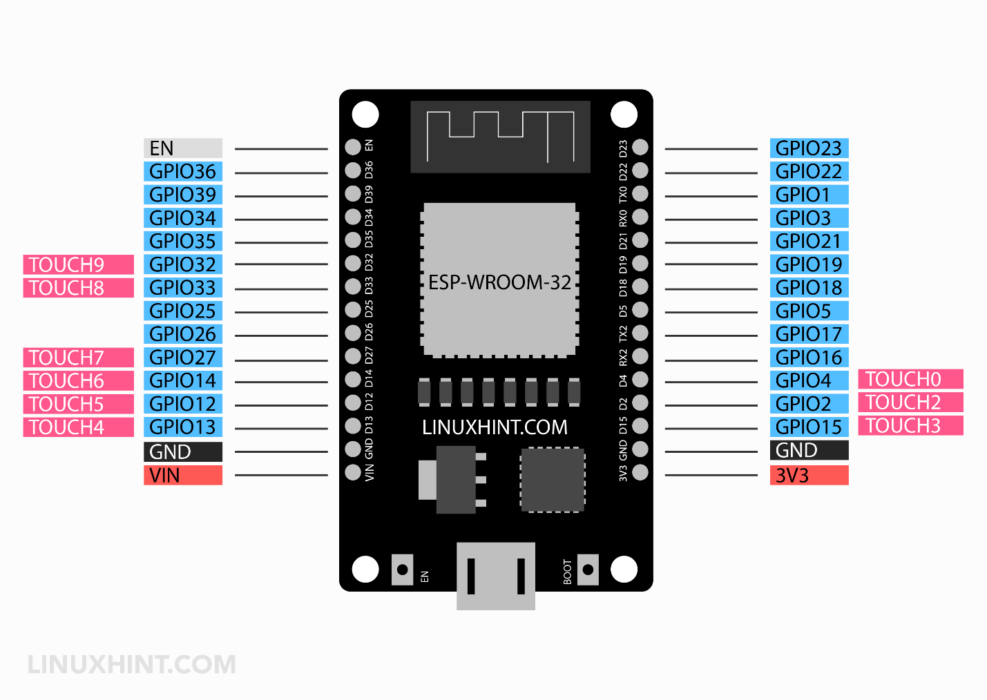
Touch_1 pin is missing in this version of ESP32 (30 pin) board. Touch_1 pin is at (GPIO0) which is present in the 36-pin ESP32.
Here is a tutorial on ESP32 Capacitive Touch Sensor with Arduino IDE.
11: ESP32 Strapping Pins
ESP32 has strapping pins that can put ESP32 into different modes like bootloader or flashing mode. In most boards that feature the built-in USB-Serial, we don’t have to worry about these pins as the board itself puts ESP32 into the right mode either flashing or boot mode.
However, in case these pins are under use, one may encounter problems in uploading new code, flashing firmware, or resetting the ESP32 board.
Below are the ESP32 strapping pins available:
-
- GPIO 0 (must be LOW to enter boot mode)
- GPIO 2 (must be floating or LOW during boot)
- GPIO 4
- GPIO 5 (must be HIGH during boot)
- GPIO 12 (must be LOW during boot)
- GPIO 15 (must be HIGH during boot)
12: Pins High at BOOT
Some GPIO pins show unexpected behavior when outputs are connected to these pins because these pins show a HIGH state or generate a PWM signal once the ESP32 board is booted or reset.
These pins are:
-
- GPIO 1
- GPIO 3
- GPIO 5
- GPIO 6 to GPIO 11 (interfaced with ESP32 internal SPI flash– Do Not use these pins for any other purpose).
- GPIO 14
- GPIO 15
13: Enable (EN) PIN
This pin is used to enable the ESP32 board. Using this we can control the ESP32 voltage regulator. This pin enables the chip when pulled HIGH and when pulled LOW, ESP32 works at minimum power.

By connecting the EN (enable) pin to GND the 3.3V on-board voltage regulator disables this meaning we can use an external pushbutton to restart ESP32 if needed.
14: ESP32 Power Pins
ESP32 has multiple power input sources. Mainly two pins can be used for powering ESP32 which include the VIN (Vin) pin and the 3V3 (3.3V) pin. The main source of powering ESP32 is using the USB cable. The other two sources required external regulated supply.
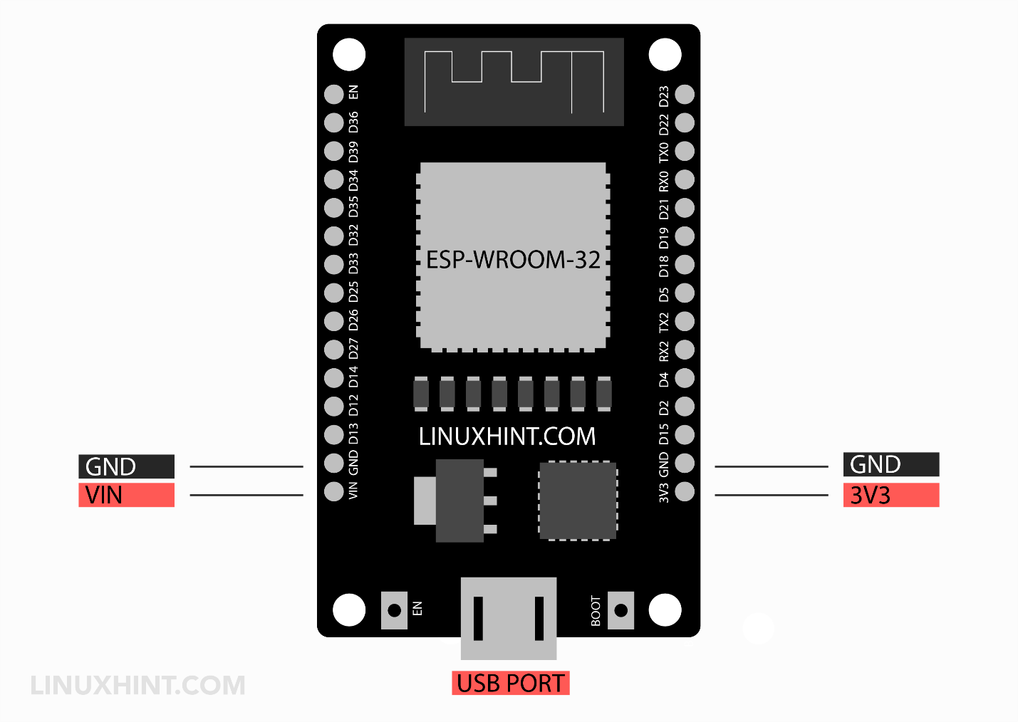
The ESP32 has an on board voltage regulator of output 3.3V which takes input from two sources USB and the VN pin after that it converts the input voltage (5V) to 3.3V for ESP32 working.
Following are the three power sources for ESP32:
-
- USB Port: Can only give input power to ESP32
- VN PIN: Works dual way input as well as output
- 3V3 PIN: Works dual way input as well as output
Note: 3V3 pin of ESP32 is not connected to on board voltage regulator it’s not recommended to use this for power input because the slight increase in voltage will result in more current flow from the output terminal of the LDO regulator (AMS1117) to the input resulting in permanent damage of ESP32 voltage regulator.
However, if you have a constant 3.3V supply then it can be used.
Secondly, do not give more than 9V to the VN pin as ESP32 only needs 3.3V for working; all remaining voltages will be dissipated as heat.
For a more detailed guide on ESP32 power sources and voltage requirements do check this tutorial How to Power ESP32.
15: ESP32 Hall Effect Sensor
ESP32 features a built-in hall effect sensor using which we can detect changes in a magnetic field and execute specific output accordingly.
Here is a tutorial on How to use ESP32 built-in Hall Effect Sensor and print the read data over the serial monitor.
Conclusion
Starting with ESP32 has never been easy but using this article on ESP32 pinout anyone can start with an IoT-based board within a few minutes. Here this article covers all the details regarding ESP32 pinout. Every ESP32 pin is discussed in extensive detail. For more tutorials on specific pins check other Tutorials on the ESP32 board.