ESP32 is a microcontroller board having multiple input output pins. ESP32 like Arduino can read and control both digital input and digital output. So here in this article we will cover how to control ESP32 output and how to read digital input from external peripherals.
How to Install ESP32 in Arduino IDE
Before we move further to our main topic, I would like to remind you to install the Arduino IDE in PC and if the ESP32 board is not installed in Arduino IDE then here is the guide on How to install ESP32 in Arduino IDE.
Digital Input Output Pins in ESP32
ESP32 boards come with a total of 48 pins which perform different functions, not all pins are physically exposed on ESP32 boards. Some pins are not available for use.
ESP32 comes in two variants, one comes with 36 pins and the second one with 30 pins. The difference of six pins here is due to SPI pins which are integrated for SPI communication and cannot be used for any other purpose.
The below pinout image is of a 30 pin ESP32 board. Most of these pins are similar to other versions such as the 36 pin ESP32 board. However, the 36 pin version of ESP32 has 6 special SPI integrated pins that are not recommended for using them as GPIO.
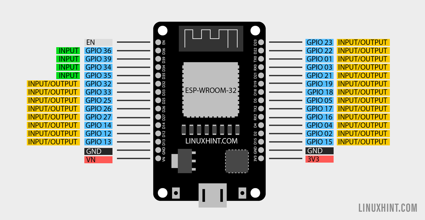
Following table illustrates the input output status of ESP32 board pins:
| GPIO PIN | INPUT | OUTPUT | Description |
| GPIO 0 | Pulled up | OK | PWM output at boot |
| GPIO 1 | Tx Pin | OK | Output debug at Boot |
| GPIO 2 | OK | OK | On board LED |
| GPIO 3 | OK | Rx Pin | High at Boot |
| GPIO 4 | OK | OK | – |
| GPIO 5 | OK | OK | PWM output at boot |
| GPIO 6 | – | – | SPI Flash Pin |
| GPIO 7 | – | – | SPI Flash Pin |
| GPIO 8 | – | – | SPI Flash Pin |
| GPIO 9 | – | – | SPI Flash Pin |
| GPIO 10 | – | – | SPI Flash Pin |
| GPIO 11 | – | – | SPI Flash Pin |
| GPIO 12 | OK | OK | Boot fail at High pull |
| GPIO 13 | OK | OK | – |
| GPIO 14 | OK | OK | PWM output at boot |
| GPIO 15 | OK | OK | PWM output at boot |
| GPIO 16 | OK | OK | – |
| GPIO 17 | OK | OK | – |
| GPIO 18 | OK | OK | – |
| GPIO 19 | OK | OK | – |
| GPIO 21 | OK | OK | – |
| GPIO 22 | OK | OK | – |
| GPIO 23 | OK | OK | – |
| GPIO 25 | OK | OK | – |
| GPIO 26 | OK | OK | – |
| GPIO 27 | OK | OK | – |
| GPIO 32 | OK | OK | – |
| GPIO 33 | OK | OK | – |
| GPIO 34 | OK | Input Only | |
| GPIO 35 | OK | Input Only | |
| GPIO 36 | OK | Input Only | |
| GPIO 39 | OK | Input Only |
Here OK means the corresponding pin can be used as input or output. All GPIO pins of ESP32 can be used as both input and output. Only SPI pins 6 to 11 cannot be used as either input or output. GPIO pins 34, 35, 36 and 39 are input only.
How to Control Digital Outputs Using Digital Pins in ESP32
As we are programming ESP32 in Arduino IDE, we will be using the same functions for declaring a pin as output as we did in the Arduino board.
To configure any digital pin we have to declare it as output using pinMode() function.
Following syntax will be followed:
Here using the above function we have declared a GPIO pin as output now to control digital output we will use digitalWrite() function.
This function takes two arguments, one is the GPIO pin number and second is the state of that pin which is to be defined. State can either be LOW or HIGH.
As explained earlier we can use all pins of ESP32 as output except GPIO 6 to 11 (SPI flash) and GPIO 34, 35, 36, and 39 (Input only).
How to Read Digital Inputs in ESP32
Reading an input from digital pins is similar to controlling an output of a pin. First we have to declare a pin as input using the pinMode() function. Following is the syntax defining a pin as input:
Once the pin is set as input, the next step is to define the digitalRead() function to get data from that pin. This is how you can define a pin as digital input.
All GPIO pins can be used as input except the SPI flash pins from 6 to 11.
Note: SPI flash pins 6 to 11 are missing in the 30 pin version of ESP32 board.
How to Control LED Using ESP32 Digital Read and Write
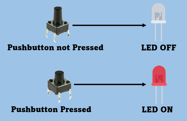
Now to clear the concept of digital read and write in ESP32 we will take an example of LED. To control the LED, we will be using a push button.
ESP32 will digitally read data from pushbutton and control a LED using the digital write command.
Hardware Required
Following is the list of components required:
- ESP32
- LED
- 2x 220 Ohm resistor
- Pushbutton
- Breadboard
- Jumper wires
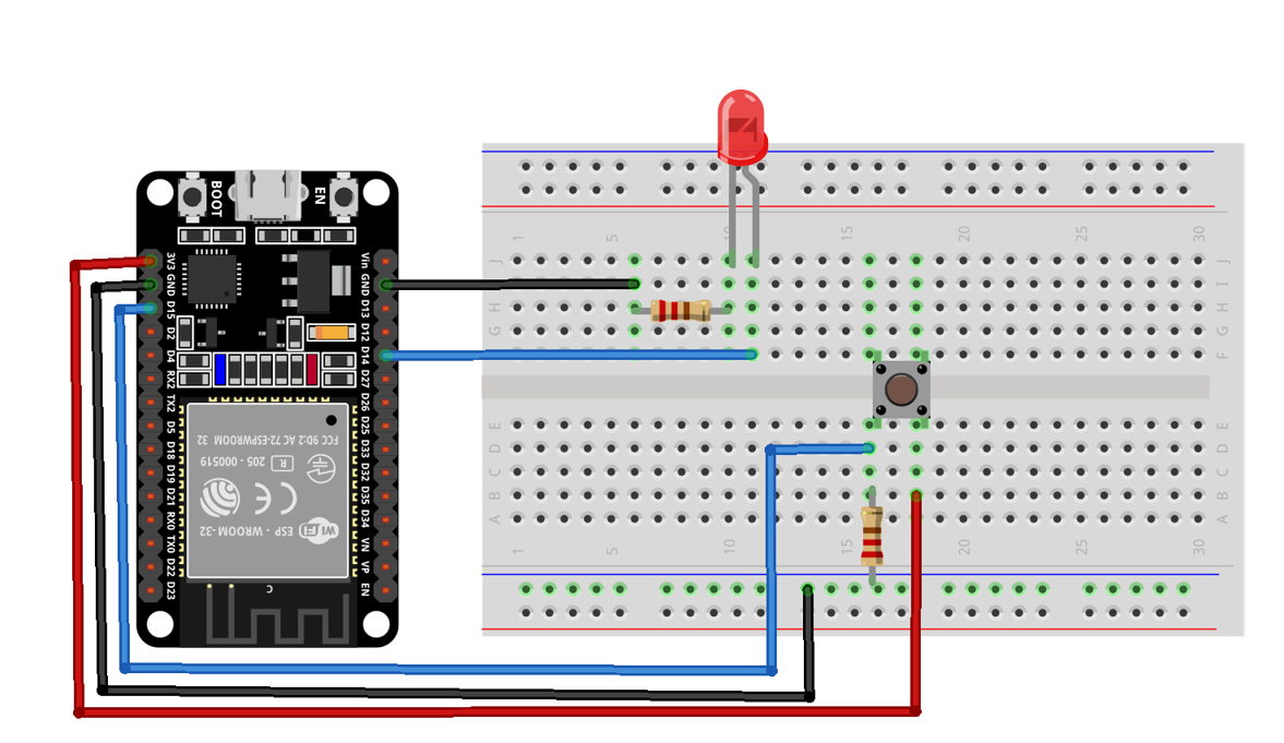
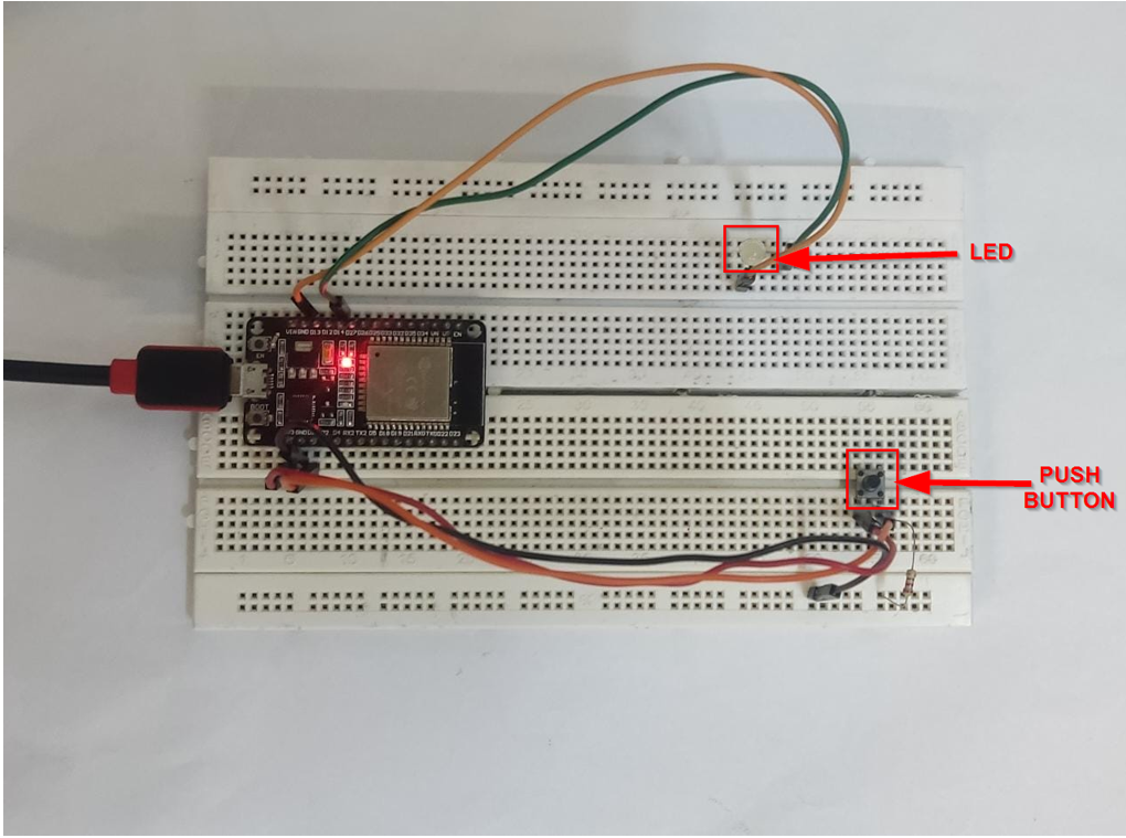
Schematic
Following image illustrates the connection of ESP32 with LED and pushbutton. The LED is connected at GPIO 14 and Pushbutton output is connected at GPIO pin 15.
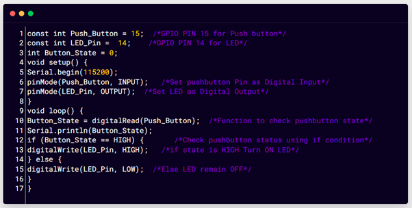
Code to Control ESP32 Digital Inputs/Outputs
Open Arduino IDE and select the ESP32 board and COM port, now upload the given code.
const int LED_Pin = 14; /*GPIO PIN 14 for LED*/
int Button_State = 0;
void setup() {
Serial.begin(115200);
pinMode(Push_Button, INPUT); /*Set pushbutton Pin as Digital Input*/
pinMode(LED_Pin, OUTPUT); /*Set LED as Digital Output*/
}
void loop() {
Button_State = digitalRead(Push_Button); /*Function to check pushbutton state*/
Serial.println(Button_State);
if (Button_State == HIGH) { /*Check push button status using if condition*/
digitalWrite(LED_Pin, HIGH); /*if state is HIGH Turn ON LED*/
} else {
digitalWrite(LED_Pin, LOW); /*Else LED remain OFF*/
}
}
Here in the above code, we started by initializing the GPIO pin for LED and pushbutton. Next, we declared LED as output and pushbutton as input to read data.
To store read data from the push button a variable is defined and at last we printed the result on the serial monitor.
Output
On hardware we can see that the LED is OFF.
Now pressing the pushbutton ESP32 board will take input from the pushbutton and set the output state of the LED to HIGH. Now the LED will turn ON.
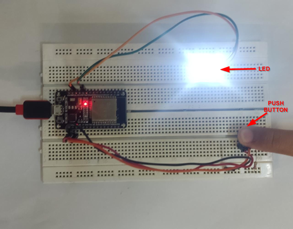
We can also see the digital data read from the pushbutton on the serial monitor of IDE.

Conclusion
ESP32 boards have multiple digital pins for input and output. Here in this article, we discussed these pins and controlled a LED using the push button. Also we have mentioned there are certain pins that can only be used as input, while some pins like SPI flash from 6 to 11 (36 version ESP32 board) can not be used either as input or output.