This article covers following content:
- 1: Introduction to Seven Segment
- 2: Seven Segment Pinout
- 3: Types of Seven Segment
- 4: How to Check a Seven Segment is Common Anode or Common Cathode
- 5: Interfacing Seven Segment with Arduino Nano
- 5.1: Schematic
- 5.2: Hardware
- 5.3: Installing the Required Library
- 6: Designing a Seven Segment 0 to 9 Counter Using Arduino Nano and Pushbutton
- 6.1: Code
- 6.2: Output
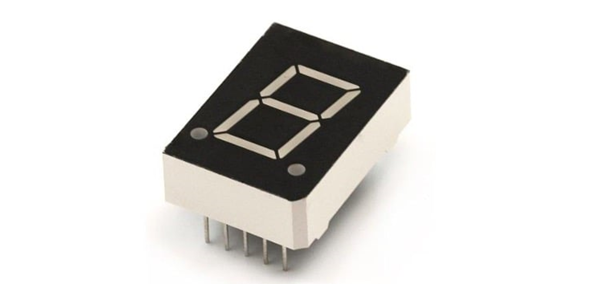
1: Introduction to Seven Segment
A seven-segment can display numerical information using a microcontroller program. It consists of seven individual segments, each of which can be lit up or turned off independently to create various numerical characters.
A seven-segment display works by illuminating different combinations of its seven segments to display numerical characters. Each segment is controlled by an individual pin, which can be turned on or off to create the desired numerical character. When the segments are illuminated in the correct combination, the numerical character is visible to the viewer.
When using an Arduino microcontroller to control a seven-segment display, the Arduino sends signals to the specific pins on the seven-segment display, telling it which segments to turn on or off in order to display a specific numerical character.
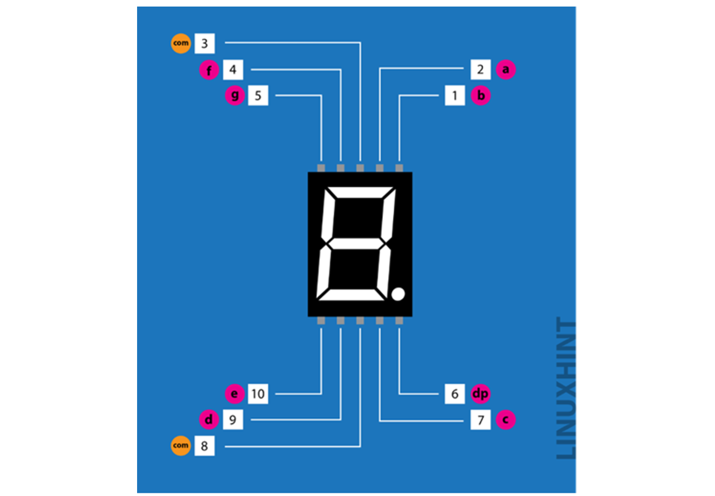
2: Seven Segment Pinout
The seven-segment display typically has 10 pins, with one pin for each segment, one for the decimal and two common pins. Here is a table of the typical pinout:
| Pin Number | Pin Name | Description |
| 1 | b | Top Right LED Pin |
| 2 | a | Topmost LED Pin |
| 3 | VCC/GND | GND/VCC Depends on Configuration – Common Cathode/Anode |
| 4 | f | Top Left LED Pin |
| 5 | g | Middle LED Pin |
| 6 | dp | Dot LED Pin |
| 7 | c | Bottom Right LED Pin |
| 8 | VCC/GND | GND/VCC Depends on Configuration – Common Cathode/Anode |
| 9 | d | Bottom LED Pin |
| 10 | e | Bottom Left LED Pin |

Each segment is labeled as a, b, c, d, e, f and g. The common pin is typically used to control all of the segments at once. The common pin is either active low or active high depending on the display.
3: Seven Segment Types
Seven segment can be categorized in 2 types:
- Common Cathode
- Common Anode.
1: In a common cathode all negative LED segment terminals are connected.
2: In a common anode seven segment all positive LED segment terminals are connected together.
4: How to Check a Seven Segment is Common Anode or Common Cathode
To check the type of seven segments we just need a simple tool – Multimeter. Follow the steps to check type of seven segment display:
- Hold the seven-segment display firmly in hand and identify pin 1 using the pinout explained above.
- Take a multimeter. Assume red lead for positive (+) and black lead of multimeter for negative (-).
- Set multimeter to continuity test.
- After that check working of the meter can be checked by touching both positive and negative leads. A beep sound will be produced if the meter is functioning properly. Otherwise replace the batteries in your multimeter with a new one.
- Put black lead on pin 3 or 8 of the multimeter. Both these pins are common and internally connected. Select any one pin.
- Now put the red or positive lead of the multimeter on other pins of seven-segments like 1 or 5.
- After touching the red probe if any segment glows the seven segment is a common cathode.
- Interchange the multimeter leads if no segment glows.
- Now connect the red lead to pin 3 or 8.
- After that put black or negative lead on the remaining pins of the display. Now if any of the segments of the display glows then the seven segments are common anode. As in COM anode all segments’ positive pins are common, and remaining are joined with negative supply.
- Repeat steps to check all other display segments one by one.
- If any of the segments does not glow, then it will be faulty.
Here is a reference image for a seven-segment test using a multimeter. We can see red lead is at COM pin 8 and black is at segment pin so we are using Common Anode seven segment: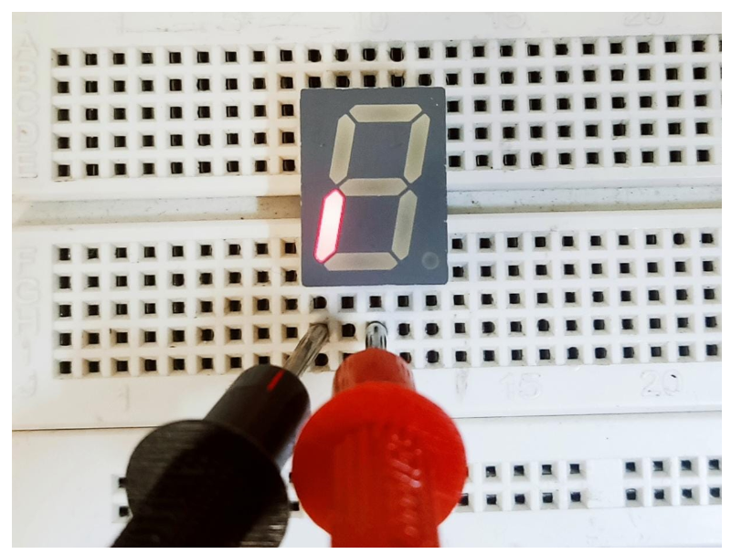
5: Interfacing Seven Segment with Arduino Nano
To interface a seven-segment display with an Arduino Nano, you will need the following materials:
- An Arduino Nano microcontroller
- A seven-segment display
- A Push button
- A breadboard
- Jumper wires
Arduino Nano interfaces with seven segment displays in several simple steps.
1: First, connect the seven-segment display to the breadboard.
2: Next, connect the Arduino Nano with a seven-segment display using wires. The Arduino Nano will be used to send signals to the seven-segment display, telling it which segments to turn on or off.
3: Now write an Arduino code in IDE. The program will need to send signals to the specific pins on the seven-segment display, telling it which segments to turn on or off in order to display a specific numerical character.
4: The Arduino IDE provides a library using which we can easily control the state of each segment with simple commands.
5: Once the program is written and uploaded to the Arduino Nano, the seven-segment display should start displaying the numerical characters as per the program.
5.1: Schematic
To design a push button counter using seven segments first we need to design the circuit given below and connect seven segments with push button and Arduino Nano. Using the below reference schematic connects your Arduino Nano board with a seven segment display.
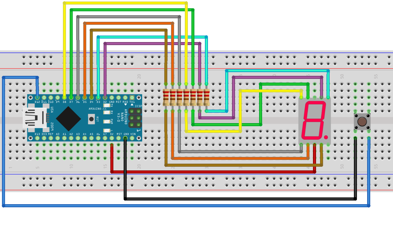
Following is the pinout table for Arduino Nano connection with a single seven segment display. A push button is also connected at D12:
| Pin Number | Pin Name | Arduino Nano Pin |
| 1 | b | D3 |
| 2 | a | D2 |
| 3 | COM | GND/VCC Depends on Configuration – Common Cathode/Anode |
| 4 | f | D7 |
| 5 | g | D8 |
| 6 | dp | Dot LED Pin |
| 7 | c | D4 |
| 8 | COM | GND/VCC Depends on Configuration – Common Cathode/Anode |
| 9 | d | D5 |
| 10 | e | D6 |
5.2: Hardware
Below image shows the hardware of Arduino Nano connected with push button and seven segment: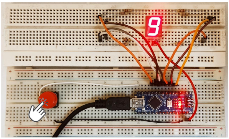
5.3: Installing the Required Library
After connecting seven segments we need to install a library in the Arduino IDE. Using this library, we can easily program Arduino Nano with seven segments.
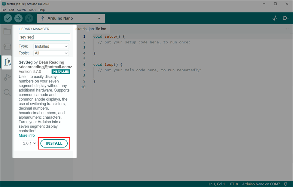
Go to Library manager search for SevSeg library and install it in Arduino IDE.
6: Designing a Seven Segment 0 to 9 Counter Using Arduino Nano and Pushbutton
To design a real time counter from 0 to 9 using Arduino Nano a push button is needed. Pushbutton will send a signal at the digital pin of Arduino Nano which will display a digit on seven segments. Every time the button is pressed one digit is incremented on seven segments.
6.1: Code
Open IDE and connect Arduino Nano. After that upload the given seven segment code to Arduino Nano:
SevSeg sevseg; /*Seven Segment Variable*/
int state1; /*Variable to store pushbutton state*/
int count=0; /*Variable that will store counter value*/
#define button1 12 /*Arduino Nano pin for pushbutton */
void setup() {
pinMode(button1,INPUT_PULLUP); /*Assign button as input*/
byte sevenSegments = 1; /*Number of seven segments we are using*/
byte CommonPins[] = {}; /*Define common pins*/
byte LEDsegmentPins[] = {2,3,4,5,6,7,8}; /*Arduino Nano digital pins defined for seven segment sequence pin a to g*/
bool resistorsOnSegments = true;
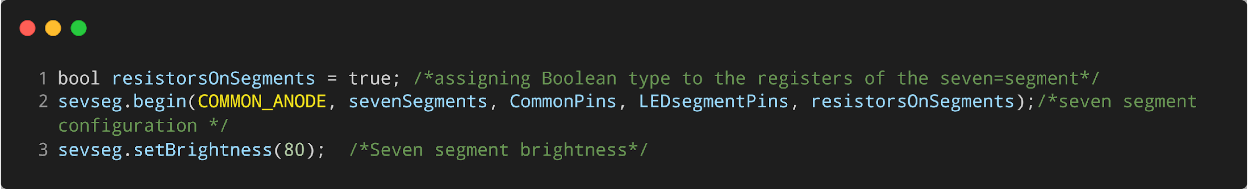
sevseg.begin(COMMON_ANODE, sevenSegments, CommonPins, LEDsegmentPins, resistorsOnSegments);/*configuration of the seven-segment */
sevseg.setBrightness(80); /*Brightness of seven segment*/
}
void loop() {
state1=digitalRead(button1); /*Read pushbutton state*/
if (state1== LOW){ /*LOW state when pushup button is pressed*/
count++; /*Increase display value by 1*/
sevseg.setNumber(count); /*display the count value*/
sevseg.refreshDisplay(); /*refresh 7-segment */
delay(300);
}
if(count == 10)
{
count = 0;
}
sevseg.setNumber(count);/*display the count value*/
sevseg.refreshDisplay();/* refresh 7-segment*/
}
Code started by calling the SevSeg library. Here we created two variables state1 and count. Both these variables will store the current state of pushbutton and seven segment value respectively.
After that we defined the number of segments we are using with Arduino Nano. LED segment pins are defined for Arduino Nano boards. Change the pin according to the type of Arduino Nano you are using.
Any of the Arduino Nano digital pins can be used.
Next as we are using the Common Anode type, so we have defined it inside the code.
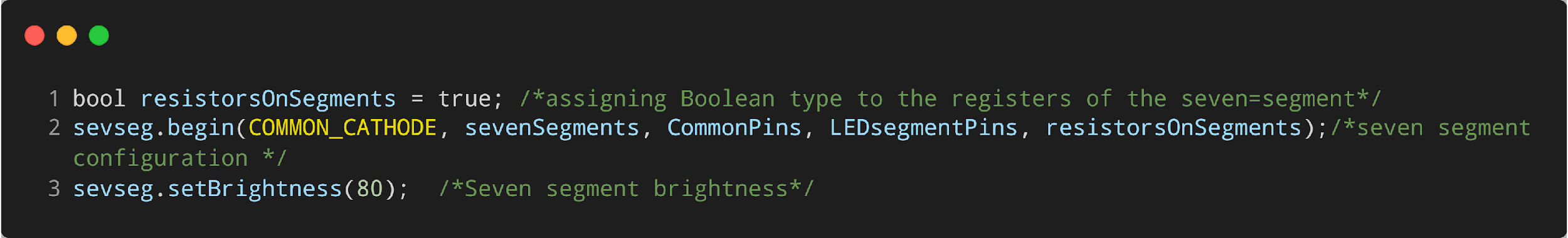
In case of Common Cathode replace it with below code.
At last, an if condition is used that will check the current state of the pushbutton and every time we press the button a value is incremented by 1. This will go on until the count variable value becomes 10. After that it will again be initialized from 0.
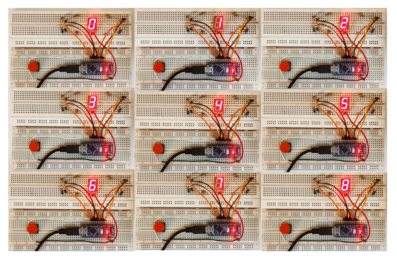
6.2: Output
Output shows digits printed from 0 to 9.
Conclusion
In conclusion, the Arduino Nano is a versatile microcontroller that can be easily programmed to create a digital counter using a seven-segment display using a push button. This setup allows for a compact and user-friendly way to display numerical data. Overall, the Arduino Nano is a powerful tool for creating simple yet effective digital counting systems.