This article covers:
- 1: Introduction to IR Sensor
- 2: IR Sensor Pinout
- 3: Interfacing IR Sensor with Arduino
- 3.1: Schematic
- 3.2: Installing the Required Library
- 4: Decoding an IR Remote Buttons
- 4.1: Code
- 4.2: Output
- 5: Controlling LED Using IR Remote
- 5.1: Schematic
- 5.2: Code
- 5.3: Output
- 6: Decoding a Smartphone Based IR Remote Using Arduino
- Conclusion
1: Introduction to IR Sensor
An IR receiver is a device that can detect and receive infrared (IR) signals. It is typically used in IR remote control systems to receive commands from a handheld remote control or other IR transmitter. The IR receiver consists of a photodiode or other IR sensitive component that detects the IR signals and a demodulator circuit that decodes the signals.
The output from the IR receiver is usually a digital signal that can be processed by a microcontroller or other electronic device.
2: IR Sensor Pinout
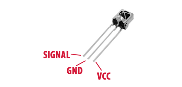
The IR receiver sensor is a small module that typically has three pins:
- VCC
- GND
- OUT
The VCC pin is connected to a power supply, such as the 5V pin on the Arduino, to provide power to the sensor. The GND pin is connected to the ground pin on the Arduino, and the OUT pin is connected to a digital input pin on the Arduino.
3: Interfacing IR Sensor with Arduino
To use the IR receiver sensor with an Arduino, a library called IRremote is required. This library can be downloaded from the Arduino website and allows the Arduino to decode the IR signals received by the sensor. Once the library is installed, it can be included in the sketch (program) that is uploaded to the Arduino.
Once the IR receiver sensor is connected and the sketch is uploaded, the Arduino can begin to receive and interpret signals from an IR remote control. The IR signals can be decoded using a function provided by the IRremote library, and the decoded signals can then be used to control various devices.
For example, a specific IR signal can be used to turn a device on or off, or to control the brightness or temperature.
3.1: Schematic
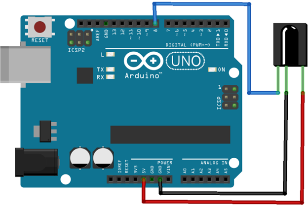
Here is a basic schematic for connecting an IR sensor to an Arduino:
| IR sensor | Arduino |
|---|---|
| VCC (power) | 5V |
| GND (ground) | GND |
| OUT (output) | D8 |
It’s important to note that different IR sensors may have different pinouts and voltages, so it’s important to check the datasheet for the specific sensor you’re using.
3.2: Installing the Required Library
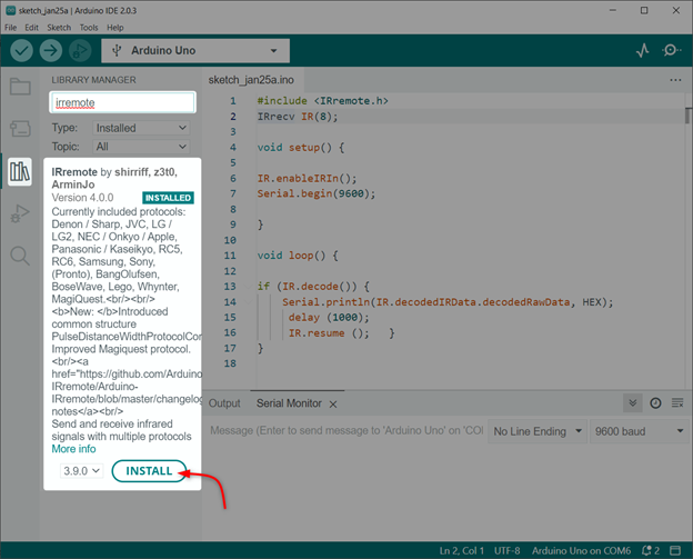
There are several IR remote libraries available for Arduino. You can use any of these libraries as per your requirement and IR remote protocol you are using.
We will install the IRremote library by ArminJo.
4: Decoding an IR Remote Buttons
There are multiple IR remotes available such as for televisions, air conditioners, and home automation systems. By decoding an IR remote we can design a universal remote for all these appliances.
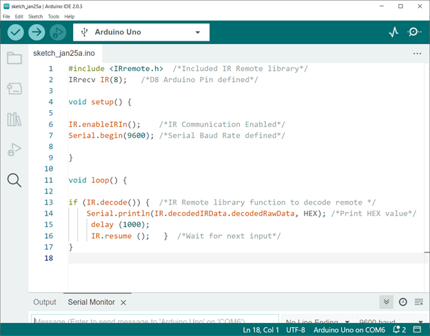
To decode an IR remote, upload the below given code and press the buttons on the IR remote then observe the serial monitor of the Arduino IDE. The example sketch will print the IR signal in HEX format and the protocol used.
Extract the key codes of the IR remote buttons you want to use in your project. Using these key codes and the IRremote library functions we can control the desired actions when the corresponding buttons are pressed on the IR remote.
4.1: Code
The Arduino Uno board can be programmed by uploading code through the Arduino IDE.
IRrecv IR(8); /*D8 Arduino Pin defined*/
void setup() {
IR.enableIRIn(); /*IR Communication Enabled*/
Serial.begin(9600); /*Serial Baud Rate defined*/
}
void loop() {
if (IR.decode()) { /*IR Remote library function to decode remote */
Serial.println(IR.decodedIRData.decodedRawData, HEX); /*Print HEX value*/
delay (1000);
IR.resume (); } /*Wait for next input*/
}
Code started by including an IR remote library. After that we defined the Arduino digital pin at which the IR signal will be read. Next in the setup() part we initialize the IR communication and baud rate is defined.
In loop() part of code we decode the received IR signal in HEX format which is then printed on serial monitor.
4.2: Output
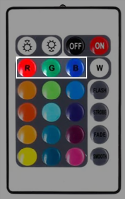
After uploading the code, we pressed three buttons Red, Green and Blue on the IR remote.
Following HEX code is obtained for the red, green and blue button on the IDE serial monitor.
| IR Remote Button | HEX Code |
|---|---|
| RED Button | 0xFB04EF00 |
| GREEN Button | 0xFA05EF00 |
| BLUE Button | 0xF906EF00 |
Using the same code any of the IR remote can be decoded.
5: Controlling LED Using IR Remote
To control a device with the IR remote, you will need to use the decoded HEX signals in your sketch. For example, you can use an if-else statement to check the decoded signal and turn on or off a specific device. You can also use the decoded signals to control the brightness or temperature of a device.
5.1: Schematic
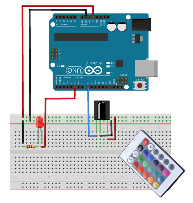
The given image explains the connection of LEDs with Arduino and IR receiver.
| LED & IR Sensor | Arduino Pin |
|---|---|
| RED LED | D5 |
| IR Sensor OUT | D8 |
5.2: Code
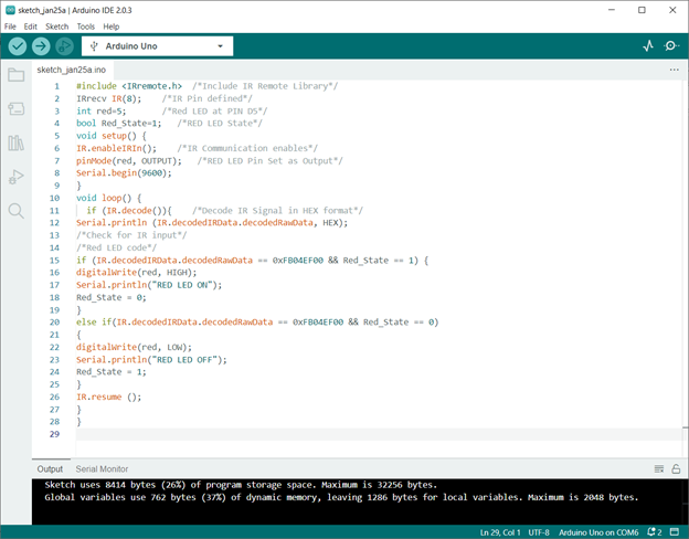
Following is the Arduino code for IR remote control LEDs. The code can be uploaded to the Arduino Uno board by opening the Arduino IDE.
IRrecv IR(8); /*IR Pin defined*/
int red=5; /*Red LED at PIN D5*/
bool Red_State=1; /*RED LED State*/
void setup() {
IR.enableIRIn(); /*IR Communication enables*/
pinMode(red, OUTPUT); /*RED LED Pin Set as Output*/
Serial.begin(9600);
}
void loop() {
if (IR.decode()){ /*Decode IR Signal in HEX format*/
Serial.println (IR.decodedIRData.decodedRawData, HEX);
/*Check for IR input*/
/*Red LED code*/
if (IR.decodedIRData.decodedRawData == 0xFB04EF00 && Red_State == 1) {
digitalWrite(red, HIGH);
Serial.println("RED LED ON");
Red_State = 0;
}
else if(IR.decodedIRData.decodedRawData == 0xFB04EF00 && Red_State == 0)
{
digitalWrite(red, LOW);
Serial.println("RED LED OFF");
Red_State = 1;
}
IR.resume ();
}
}
Code started by including an IR remote library. After that we defined the Arduino digital pin at which the IR signal will be read. Next a red LED is defined.
In the setup() part we initialize the IR communication and baud rate is defined. Along with that LED pin is set as output using pinMode() function.
In loop() part of code if-else condition is used for red LED. You can set any of the IR remote buttons by describing the HEX value inside the code.
| IR Remote Button | HEX Code |
|---|---|
| RED Button | 0xFB04EF00 |
| GREEN Button | 0xFA05EF00 |
| BLUE Button | 0xF906EF00 |
Note: Remember these are the HEX code for the remote one we are using. Your remote may have a different HEX code. So, replace the code with HEX code you got in the serial monitor.
5.3: Output
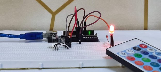
After uploading code to the Arduino board press the red button and the LED will glow.
To turn OFF the LED simply press the button again as we have used the toggle condition in Arduino code.
Using the same method, we can control AC appliances by replacing the LED with a Relay switch.
6: Decoding a Smartphone Based IR Remote Using Arduino
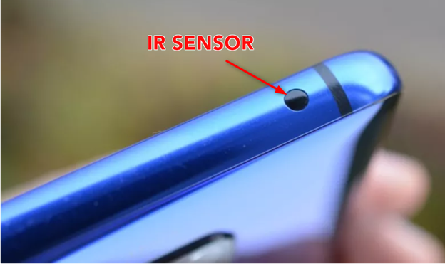
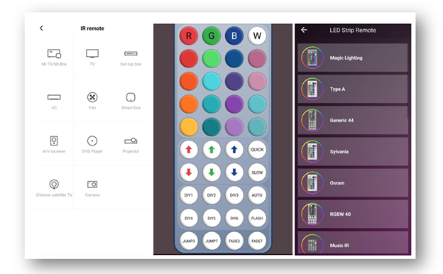
If your smartphone has an IR sensor you can design a custom remote control to control devices and appliances. First, we have to decode the smartphone-based IR remote using Arduino, you will need an IR receiver module, an Arduino board.
Using the above given code we can easily decode any IR remote present in smartphones and can also design a custom one.
Following are some sample images of IR remote present in smartphones.
Conclusion
In summary, decoding an IR remote control with an Arduino microcontroller is a simple and cost-effective way to control various devices. By connecting an IR receiver to the Arduino, uploading a sketch, and decoding the IR signals, you can easily control devices such as televisions, air conditioners, and home automation systems.

