This article sums up the following points:
1: Introduction to Arduino GUI
2: Designing Arduino GUI for LED Control
1: Introduction to Arduino GUI
The Arduino GUI, or graphical user interface, is a platform that allows users to easily interact with the physical world through the use of sensors and other electronic components. With the help of the GUI, users can create custom graphical interfaces to control their devices, monitor sensor data, and visualize results in real-time.
Having an Arduino project with GUI helps users having different levels of technical expertise to control and monitor their project. There are multiple platforms that design Arduino GUI and one of those is Processing. Using this we can install libraries and create a custom GUI for our project.
2: Designing Arduino GUI for LED Control
The design of a graphical user interface (GUI) for an Arduino system can be achieved using the Processing programming language. This combination provides a user-friendly interface for interacting with the physical world via the microcontroller.
Processing offers a simple environment for creating graphical elements and animations, while Arduino provides the hardware interaction and control.
To design Arduino based GUI for LED control we will use the processing software. Using the processing we will design GUI and link it with Arduino code using the serial Arduino communication.
First step is to download the processing and install it in the system.
2.1: Download Processing
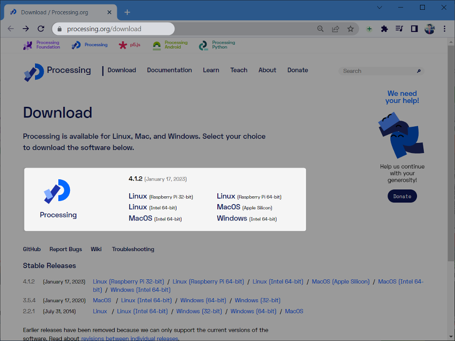
Go to the Processing official site and download it.
Step 1: Download the processing according to your operating system:
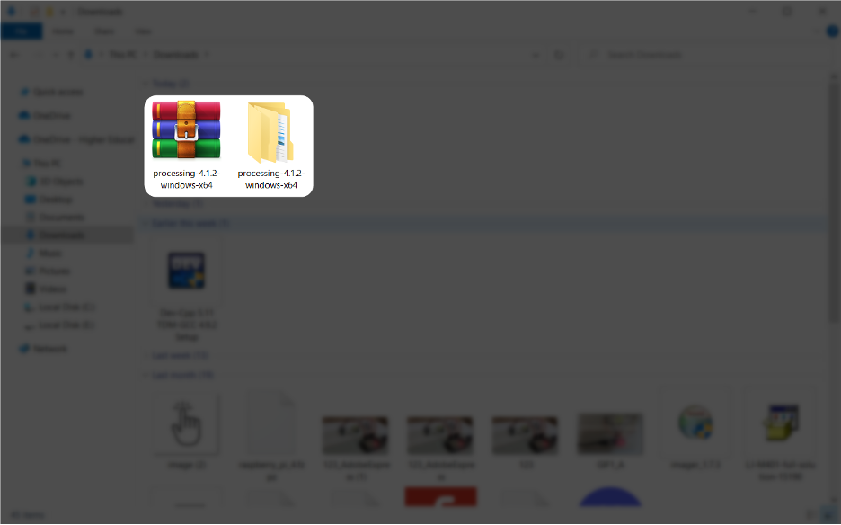
Step 2: After downloading it, extract the file:
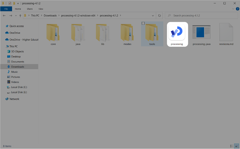
Step 3: Once the zip file is extracted run the exe Processing installer. After successful installation, open it using the start button or through a shortcut:
2.2: Installing ControlP5 Library in Processing
ControlP5 is a library for the Processing programming environment and for Arduino that provides GUI controls for interactive programs. It provides a set of GUI widgets (e.g buttons, sliders, knobs) and tools for creating graphical user interfaces for Processing and Arduino projects.
Before we control the Arduino, we need to install it in Processing software.
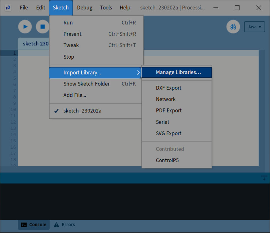
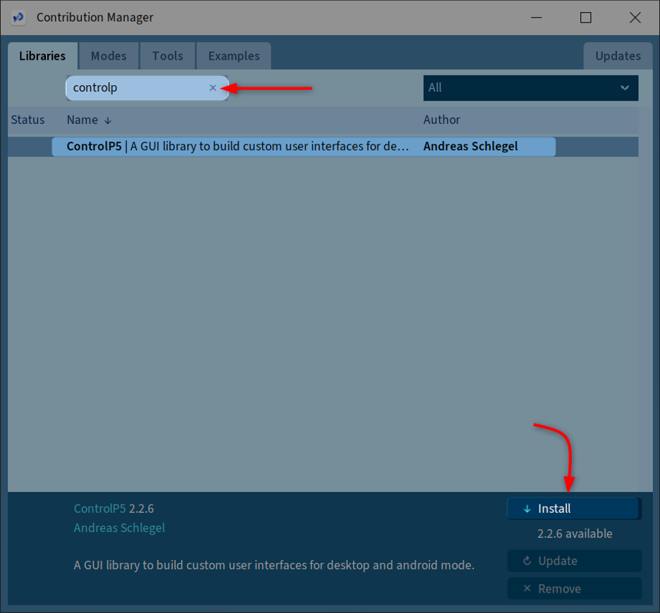
Step 1: Open Processing and go to: Sketch>Import Library>Manage Library:
Step 2: Search for the ControlP5 library and click install:
After successful installation of the ControlP5 library we can easily program Arduino with Processing and create an interactive GUI for different projects.
2.3: Schematic
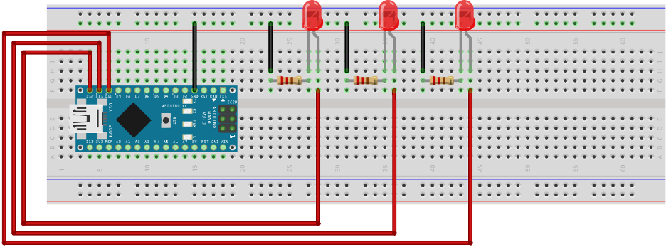
We are going to design a Processing GUI for the Arduino LED control program. Connect three LEDs at pin D10,11 and 12. Here we are using the Arduino Nano board. You can go with any of the Arduino boards:
3: Processing Code for GUI
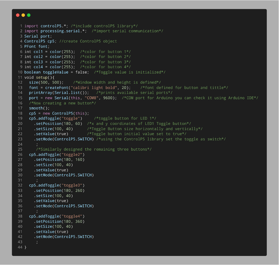
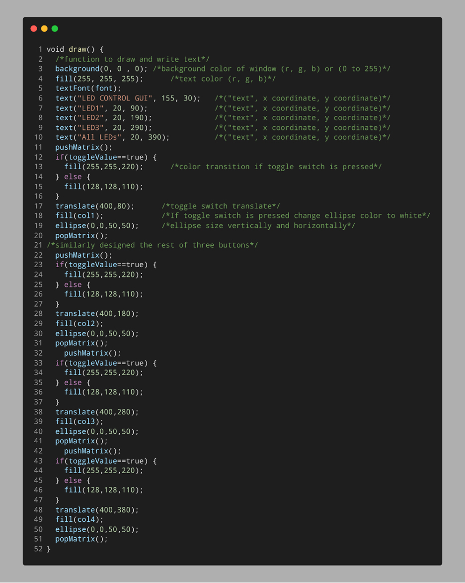
Following is the processing code for Arduino GUI. This code helps to control three different LEDs using a simple graphical interface.
import processing.serial.*; /*import serial communication*/
Serial port;
ControlP5 cp5; //create ControlP5 object
PFont font;
int col1 = color(255); /*color for button 1*/
int col2 = color(255); /*color for button 2*/
int col3 = color(255); /*color for button 3*/
int col4 = color(255); /*color for button 4*/
boolean toggleValue = false; /*Toggle value is initialized*/
void setup(){
size(500, 500); /*Window width and height is defined*/
font = createFont("calibri light bold", 20); /*font defined for button and tittle*/
printArray(Serial.list()); /*prints available serial ports*/
port = new Serial(this, "COM8", 9600); /*COM port for Arduino you can check it using Arduino IDE*/
/*Now creating a new button*/
smooth();
cp5 = new ControlP5(this);
cp5.addToggle("toggle") /*toggle button for LED 1*/
.setPosition(180, 60) /*x and y coordinates of LED1 Toggle button*/
.setSize(100, 40) /*Toggle Button size horizontally and vertically*/
.setValue(true) /*Toggle button initial value set to true*/
.setMode(ControlP5.SWITCH) /*using the ControlP5 library set the toggle as switch*/
;
/*Similarly designed the remaining three buttons*/
cp5.addToggle("toggle2")
.setPosition(180, 160)
.setSize(100, 40)
.setValue(true)
.setMode(ControlP5.SWITCH)
;
cp5.addToggle("toggle3")
.setPosition(180, 260)
.setSize(100, 40)
.setValue(true)
.setMode(ControlP5.SWITCH)
;
cp5.addToggle("toggle4")
.setPosition(180, 360)
.setSize(100, 40)
.setValue(true)
.setMode(ControlP5.SWITCH)
;
}
void draw() {
/*function to draw and write text*/
background(0, 0 , 0); /*background color of window (r, g, b) or (0 to 255)*/
fill(255, 255, 255); /*text color (r, g, b)*/
textFont(font);
text("LED CONTROL GUI", 155, 30); /*("text", x coordinate, y coordinate)*/
text("LED1", 20, 90); /*("text", x coordinate, y coordinate)*/
text("LED2", 20, 190); /*("text", x coordinate, y coordinate)*/
text("LED3", 20, 290); /*("text", x coordinate, y coordinate)*/
text("All LEDs", 20, 390); /*("text", x coordinate, y coordinate)*/
pushMatrix();
if(toggleValue==true) {
fill(255,255,220); /*color transition if toggle switch is pressed*/
} else {
fill(128,128,110);
}
translate(400,80); /*toggle switch translate*/
fill(col1); /*If toggle switch is pressed change ellipse color to white*/
ellipse(0,0,50,50); /*ellipse size vertically and horizontally*/
popMatrix();
/*similarly designed the rest of three buttons*/
pushMatrix();
if(toggleValue==true) {
fill(255,255,220);
} else {
fill(128,128,110);
}
translate(400,180);
fill(col2);
ellipse(0,0,50,50);
popMatrix();
pushMatrix();
if(toggleValue==true) {
fill(255,255,220);
} else {
fill(128,128,110);
}
translate(400,280);
fill(col3);
ellipse(0,0,50,50);
popMatrix();
pushMatrix();
if(toggleValue==true) {
fill(255,255,220);
} else {
fill(128,128,110);
}
translate(400,380);
fill(col4);
ellipse(0,0,50,50);
popMatrix();
}
/*function to turn ON and OFF LED*/
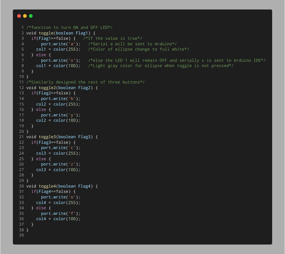
void toggle(boolean Flag1) {
if(Flag1==false) { /*If the value is true*/
port.write('a'); /*Serial a will be sent to Arduino*/
col1 = color(255); /*Color of ellipse change to full white*/
} else {
port.write('x'); /*else the LED 1 will remain OFF and serially x is sent to Arduino IDE*/
col1 = color(100); /*Light gray color for ellipse when toggle is not pressed*/
}
}
/*Similarly designed the rest of three buttons*/
void toggle2(boolean Flag2) {
if(Flag2==false) {
port.write('b');
col2 = color(255);
} else {
port.write('y');
col2 = color(100);
}
}
void toggle3(boolean Flag3) {
if(Flag3==false) {
port.write('c');
col3 = color(255);
} else {
port.write('z');
col3 = color(100);
}
}
void toggle4(boolean Flag4) {
if(Flag4==false) {
port.write('o');
col4 = color(255);
} else {
port.write('f');
col4 = color(100);
}
}
The above code started by including the ControlP5 library along with a serial communication file. Next we defined 4 different variables that will store the colors for different button states.
In the setup part the GUI window size is defined. Next a COM port is defined for serial communication with the Arduino board. You can check the COM port using the Arduino IDE.
Next, we defined four different buttons: their size and position. All of these four buttons’ initial value is set to true. The first three buttons will individually control a LED while the fourth button will toggle all three LEDs at once.
Next in the void draw function we designed the ellipse indicator for four buttons. When each of the toggle buttons is pressed the ellipse color will shift to full brightness showing us the LED is turned ON.
Using the pushMatrix() and popMatrix() function we initialized an IF condition for each of the toggle switches. When any of the toggle buttons is pressed it will translate and the ellipse will change its color to 255.
At the start of the program, we defined a separate color state for each of the ellipses corresponding to a specific button.
And at last a void function for each of the toggle buttons is defined. This function will serially send a specific character to the Arduino board when a toggle switch is pressed.
For example, if the toggle2 value is false a character b will be transmitted serially to Arduino. Which will turn ON the LED at pin D11. Similarly, if the toggle2 value is true a character y will be transmitted serially which will turn the LED at pin D11 to OFF.
Following tables give us an idea about how these serial characters are working:
| Serial Character | Output Response |
|---|---|
| a | Turn ON LED at PIN D10 |
| b | Turn ON LED at PIN D11 |
| c | Turn ON LED at PIN D12 |
| x | Turn OFF LED at PIN D10 |
| y | Turn OFF LED at PIN D11 |
| z | Turn OFF LED at PIN D12 |
Note: We can customize these characters to any other but make sure to use the same characters in both Arduino and Processing code.
4: Arduino IDE Code for GUI
Following is the Arduino code written in Arduino IDE:
pinMode(10, OUTPUT); /*Pin for LED1*/
pinMode(11, OUTPUT); /*Pin for LED2*/
pinMode(12, OUTPUT); /*Pin for LED3*/
Serial.begin(9600); /*Serial Baud rate*/
}
void loop(){
if(Serial.available()){ /*Check for serial data availability from processing*/
char val = Serial.read(); /*if serial data is available store it inside a variable*/
if(val == 'a'){ /*if a received*/
digitalWrite(10, HIGH); /*turn ON LED1*/
}
if(val == 'b'){ /*if b received*/
digitalWrite(11, HIGH); /*turn ON LED2*/
}
if(val == 'c'){ /*if c received*/
digitalWrite(12, HIGH); /*turn ON LED3*/
}
if(val == 'x'){ /*if x received*/
digitalWrite(10, LOW); /*turn OFF LED1*/
}
if(val == 'y'){ /*if y received*/
digitalWrite(11, LOW); /*turn OFF LED2*/
}
if(val == 'z'){ /*if z received*/
digitalWrite(12, LOW); /*turn OFF LED3*/
}
if(val == 'o'){ /*if o received*/
digitalWrite(10, HIGH);
digitalWrite(11, HIGH); /*turn ON all LEDs*/
digitalWrite(12, HIGH);
}
if(val == 'f'){ /*if f received*/
digitalWrite(10, LOW);
digitalWrite(11, LOW); /*turn OFF all LEDs*/
digitalWrite(12, LOW);
}
}
}
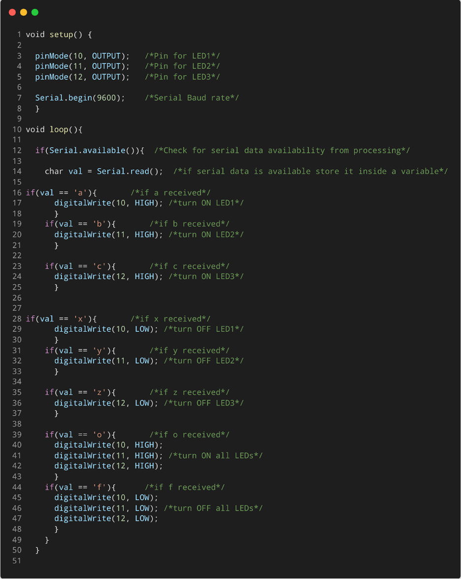
This code started by defining the pin for three LEDs. Each of these pins is defined as output using the pinMode() function. Next Arduino code will continuously check for the serial data. If the serial data is available it will generate a response according to that.
For example if the Processing GUI toggle switch 1 is pressed a character “a” will be received by Arduino and it will turn on LED at pin D10. Similarly if the character “x” is received serially it will turn OFF the LED at pin D10:
5: Output
After uploading code to the Arduino board, run the Processing code and make sure the Arduino board is serially connected with the PC.
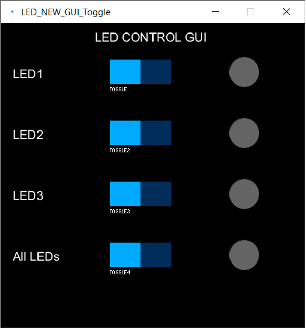
Following window will open showing us the GUI designed for three LEDs. Using this GUI we can control any of the LEDs by sampling toggling the switch:
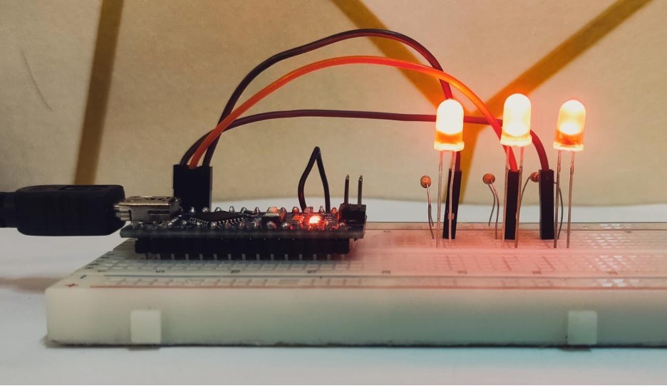
We can control LED glow using this GUI:
Conclusion
The use of the ControlP5 library in combination with Processing and Arduino offers a powerful solution for creating GUI-based projects. The library provides a comprehensive set of tools and widgets that simplify the process of creating user-friendly graphical interfaces, allowing developers to focus on their project’s core functionality.

