What are Stepper Motors?
Stepper motors are brushless and synchronous motors which can divide its full rotation cycle into a number of discrete steps. Unlike other brushless DC motors that run continuously when a fixed DC voltage is applied across them Step motors can divide their rotatory movement into a number of steps according to a digital pulse.
Stepper Motor Types
Two types of stepper motors are generally used:
- Bipolar
- Unipolar
Most of the time we can distinguish between these two motors by looking at the number of wires. A stepper motor with 6 wires can be classified as Unipolar and a 4 wires motor can be classified as Bipolar. Main difference between them is the center tap wire which splits full coil winding into half winding.
Controlling these stepper motors requires motor drivers. Most commonly used drivers include ULN2003, L298N and A4988. In this article we will proceed with a bipolar motor-controlled driver known as A4988 motor driver.
Components Required
Following components are required to control stepper motor with Arduino:
- Arduino UNO
- USB B cable
- Stepper Motor (Bipolar)
- Jumper wires
- Motor Driver (A4988)
- 100uF Capacitor
- Power supply (8-35V)
- Breadboard
Why use Motor Driver
Generally, stepper motors are hard to control using Arduino pins. They draw current over 20mA due to electromagnetic behavior of motors which exceeds the current limit of Arduino pins. Another problem is kickback voltage, due to electromagnetic nature, motors continue to generate electricity even after the power cuts, this will create enough negative voltage than can fry your Arduino.
Solution to this is use of motor driver chips or shields. Motor drivers have diodes that prevent Arduino from negative voltages and transistor-based circuits that provide enough power to run the motor.
A4988 Driver Module
A4988 is one of the best dedicated motor controllers available. This integrated motor controller makes it super easy to interfacing with a microcontroller, as only two pins are enough to control speed and direction of stepper motor. Using dedicated motor controller has many advantages:
- Motor driver controlled the stepping logic itself, freeing the Arduino to do other things.
- Number of connections is reduced which helps in controlling multiple motors with a single board.
- Possible to control the motor even without any microcontroller by using simple square waves.
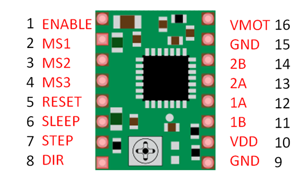
A4988 Pinout
Total 16 pins are there in A4988 driver as follows:
Wiring Diagram: Connecting A4988 with Arduino UNO and Stepper Motor
Connect stepper motor with Arduino by following the below-mentioned circuit:
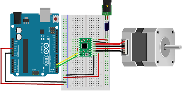
Note: A4988 motor driver is equipped with a Low-ESR ceramic capacitor which cannot handle LC voltage spikes. It is better to use an electrolytic capacitor between the VMOT & GND pins, here we have used a 100uF capacitor after the power supply.
A4988 Connections
| A4988 | Connection |
|---|---|
| VMOT | 8-35V |
| GND | Motor GND |
| SLP | RESET |
| RST | SLP |
| VDD | 5V |
| GND | Logic GND |
| STP | Pin 3 |
| DIR | Pin 2 |
| 1A,1B,2A,2B | Stepper Motor |
How to Set the Current Limit for Stepper Motor
Before connecting the Arduino with the stepper motor it’s important to set the current limit of the motor driver lower than the stepper motor current rating, otherwise the motor will heat up.
A small potentiometer present on A4988 driver can set current limit, as shown in image. On clockwise rotation current limit increases and on anticlockwise rotation current limit decreases.

How to code Stepper motor with Arduino
Now that we have completed our circuit and set the current limit for motor drivers, it’s time to control stepper motors with the help of Arduino. Upload the following code to the Arduino board using IDE as this code does not require any standard library to run.
#define direction 2
#define step 3
#define stepsinOneRevolution 200
void setup() {
// Declare pins as output:
pinMode(step, OUTPUT);
pinMode(direction, OUTPUT);
}
void loop() {
digitalWrite(direction, HIGH); // Motor will spin clockwise
// Motor will complete one revolution slowly
for (int i = 0; i < stepsinOneRevolution; i++) {
digitalWrite(step, HIGH);
delayMicroseconds(2000);
digitalWrite(step, LOW);
delayMicroseconds(2000);
}
delay(1000);
digitalWrite(direction, LOW); // Motor will spin Anticlockwise
// Motor will complete one revolution quickly
for (int i = 0; i < stepsinOneRevolution; i++) {
digitalWrite(step, HIGH);
delayMicroseconds(1000);
digitalWrite(step, LOW);
delayMicroseconds(1000);
}
delay(1000);
}
Code explanation
We will start our sketch by defining step and direction pins. Here I used them with Arduino pins 2 and 3. The constant stepsinOneRevolution is defined along with its value 200, I set the motor driver at its full step mode 200 steps per revolution.
#define step 3
#define stepsinOneRevolution 200
In the setup() section, by using pinMode() function motor control pins are set as digital OUTPUT.
pinMode(step, OUTPUT);
pinMode(direction, OUTPUT);
}
In the loop() section, the motor will complete one revolution slowly in clockwise and one revolution quickly in anticlockwise. This is because we have set digitalWrite() as HIGH and LOW alternatively and decreasing delayMicroseconds() from 2 milliseconds to 1 milliseconds.
Look at the code shown below, digitalWrite(direction, HIGH); is set to HIGH value, the motor will spin clockwise.
The delayMicroseconds() is set to 2 milliseconds, the motor will spin slowly.
void loop() {
digitalWrite(direction, HIGH); // Motor will spin clockwise
// Motor will complete one revolution slowly
for (int i = 0; i < stepsinOneRevolution; i++) {
digitalWrite(step, HIGH);
delayMicroseconds(2000);
digitalWrite(step, LOW);
delayMicroseconds(2000);
}
Similarly, in this section Motor will spin faster due to less delay in milliseconds, but in opposite direction (Anticlockwise) due to LOW value of digitalWrite(direction, LOW):
// Motor will complete one revolution quickly
for (int i = 0; i < stepsinOneRevolution; i++) {
digitalWrite(step, HIGH);
delayMicroseconds(1000);
digitalWrite(step, LOW);
delayMicroseconds(1000);
}
Control Motor speed
Speed is determined by frequency of the pulse generated at step pin; we can control frequency of pulse by changing:
Shorter delay means higher frequency and faster the motor runs.
Control spinning direction
Spinning direction of motor is controlled by setting the direction pin either HIGH or LOW, we use following function to do this:
digitalWrite(direction, LOW); //Anticlockwise
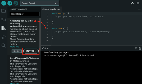
As in the above example, we have not used any Arduino library but you can use the stepper motor library in Arduino IDE. Another very famous library available in IDE mostly used for stepper motors is AccelStepper.h. You can include that library by following this Path:
Go to Sketch>Include Library>Manage Libraries>Search>AccelStepper>Install:
Conclusion
This tutorial has shown you that steppers motors are not so hard to work with. We have covered the main aspects of controlling a stepper motor with the help of Arduino and Motor driver. So, if you are planning a project that requires you to position something precisely then a stepper motor will be an ideal choice.