- What is Arduino Zero
- Specifications of Arduino Zero
- Features of Arduino Zero
- Programming Language for Arduino Zero
- Programming the Arduino Zero Board
- ARM Core Benefits
- Atmel Embedded Debugger
- Power
- Arduino Zero Power Pins
- Memory
- Input and Output
- Conclusion
1. What is Arduino Zero
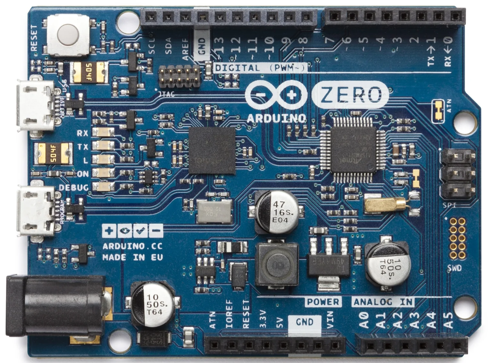
The Arduino Zero board is an Atmel SAMD21 based board, which is the first 32-bit Arduino board. It was introduced in 2015 and is designed to provide a powerful platform for developers to build IoT applications. The board is compatible with the Arduino Software (IDE), and it can be programmed using the same Arduino syntax as the other Arduino boards. It is a highly versatile board that can be used for a wide range of applications, including robotics, automation, and more.
2. Specifications of Arduino Zero
The Arduino Zero board has the following specifications:
| Microcontroller | ATSAMD21G18, 32-Bit ARM® Cortex® M0+ |
| Operating Voltage | 3.3V |
| Digital I/O Pins | 20 |
| PWM Pins | 3, 4, 5, 6, 8, 9, 10, 11, 12, 13 |
| UART | 2 (Native and Programming) |
| Analog Input Pins | 6, 12-bit ADC channels |
| Analog Output Pins | 1, 10-bit DAC |
| External Interrupts | All pins except pin 4 |
| DC Current per I/O Pin | 7 mA |
| Flash Memory | 256 KB |
| SRAM | 32 KB |
| EEPROM | None. See documentation |
| LED_BUILTIN | 13 |
| Clock Speed | 48 MHz |
| Length | 68 mm |
| Width | 53 mm |
| Weight | 12 gr. |
3. Features of Arduino Zero
The Arduino Zero board offers several features that make it a highly versatile and powerful board:
- 32-bit ARM Cortex-M0+ core
- It has a 256 KB Flash memory and a 32 KB of SRAM
- 12-bit ADC and 12 PWM outputs
- USB 2.0 Host/Device Port
- 3.3V logic level
- EDBG debugging interface
4. Programming Language for Arduino Zero
The programming language used for programming the Arduino Zero board is C++. The Arduino Zero board can be programmed using the Arduino Software (IDE), which is available for Windows, macOS, and Linux. The software provides a code editor, a compiler, and a serial monitor, making it easy to write, compile, and debug code.
5. Programming the Arduino Zero Board
Uploading code to the Arduino Zero is different from the normal Arduino boards. As Arduino Zero is based on SAMD21 which is different from the AVR microcontroller, as most of the popular Arduino boards are based on AVR structure.
Arduino Zero comes with two UART ports, one is native and the other one is a programming port. To upload sketches to board it is recommended to use the programming port instead of native port. This is due to its ability to erase the data on chip once code is uploaded.
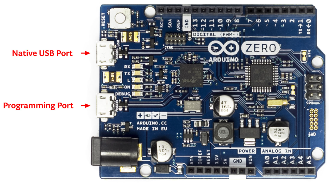
- Programming port: In Arduino Zero this port uses the EDBG and can program the board using the USB-to-SWD. To program Arduino Zero using this port select it from the IDE port section and connect this port with the PC using a USB cable. For reference this port is closer to the DC jack as highlighted in image above.
- Native port: The native port is connected directly to the SAMD21 microcontroller on the board. To use native port, select it from the IDE port section and after that use the USB cable to build the connection of Arduino Zero with the PC using this port. This port is located on the left side of the reset button as highlighted in the above image.
Like other boards which are based on avrdude for uploading code to microcontroller. The Arduino Zero relies on bossac and the Arduino Zero programming port uses openOCD.
6. ARM Core Benefits
The Arduino Zero is based on a 32-bit ARM core while other microcontrollers use the 8-bit AVR structure. The ARM core is more advanced in working than AVR structure. Here are some main highlights:
- The ARM core has a CPU Clock at 48MHz.
- Arduino zero ARM core has a 12 channels DMA controller that helps the CPU in memory intensive tasks.
- Arduino Zero can handle the 4-byte data very easily using the 32-bit ARM core over the single CPU clock.
- It has 32-bit RTC with clock/calendar support.
- It comes with a 32-bit CRC generator.
- The ARM core has a two-channel (I2S) interface.
- It has a built-in Peripheral Touch Controller (PTC).
7. Atmel Embedded Debugger
The Arduino Zero board includes an Atmel Embedded Debugger (EDBG) chip that provides a range of debugging and programming functions.
The EDBG chip on the Arduino Zero board can be used to program and debug the board via the programming port, which is the port closest to the DC power jack. The programming port uses the EDBG chip as a USB-to-SWD (Serial Wire Debug) converter, allowing you to program and debug the SAMD21 microcontroller using the SWD protocol.
In addition to the programming and debugging features, the EDBG chip on the Arduino Zero board also provides a Virtual COM port interface, allowing you to communicate with the board via the native USB port, which is the port closest to the reset button. This interface can be used for different protocols in Arduino Zero like UART, SPI, and I2C.
8. Power
The Arduino Zero has two different sources of power just like Arduino Uno:
- USB connector
- External power supply
The board is intelligent enough to automatically select the power source, making it easy for you to switch between power modes.
External Power Sources for the Arduino Zero
External power sources for the Arduino Zero can come from an AC-to-DC adapter or battery. To connect an external power source, a 2.1mm center-positive plug can be used with an Arduino Zero DC barrel jack. We can also connect external power sources directly with the VIN pin as we do in Arduino Uno. This gives you the flexibility to choose the most suitable power source for your project.
Voltage Range for the Arduino Zero
The Arduino Zero voltage that it can take as mentioned on its datasheet is between 6 to 20 volts, but it’s recommended to not use more than 12V as it can cause overheating on the voltage regulator as a result of excess voltage loss during conversion to 3.3V.
Operating outside of this range could result in damage to the board or underperformance of your project. It is important to note that the voltage of the external power source will affect the board’s performance, so it’s essential to choose the right power source for your project.
9. Arduino Zero Power Pins
Arduino zero has a diverse range of power sources. It can be powered up using following different sources:
VIN Pin: Powering the Board
When you’re using an external power source to operate the Arduino Zero board, the VIN pin comes in handy. This pin is responsible for receiving voltage input to the board. Additionally, if you’re supplying voltage through the power jack, you can access it via this pin as well.
5V Pin: Regulated Voltage Output
The Arduino Zero board has a built-in regulator that outputs a regulated 5V through the 5V pin. Arduino Zero can be directly connected to 7V to 12V using a DC jack or VIN pin. This voltage is then passed through a regulator which converts it into 5V. These 5V can be used as a power source for 5V operating sensors. However, be careful not to supply voltage via the 5V or 3.3V pins as it can bypass the regulator and cause damage to the board.
3.3V Pin: On-board Regulator
The on-board regulator generates a 3.3V supply for the board. This 3.3V is given to onboard peripherals including the SAMD21 microcontroller. This 3.3V can also be output from the onboard 3.3V pin and the maximum amount of current we can draw from Arduino Zero 3.3V pin is 800mA.
GND Pin: Grounding the Board
The Zero board has multiple ground pins (GND) that help to establish a ground connection. You can use them to ground the components you’re connecting to the board.
IOREF Pin: Voltage Reference
The IOREF pin provides the voltage reference for the microcontroller’s operation. This pin helps the Arduino Zero board to select the best power source for its working. It also enables the voltage translator that helps the Arduino board to work with 3.3V.
10. Memory
The memory distribution of Arduino Zero (SAMD21) is as follows:
| Memory | Value |
| Flash Memory | 256 KB |
| SRAM | 32 KB |
| EEPROM | 16 KB |
11. Input and Output
The Arduino Zero has a total of 20 general purpose I/O pins. Following are some specifications of these GPIO pins:
- Arduino Zero pins can be controlled with the Arduino programming functions such as pinMode(), digitalWrite(), and digitalRead().
- Arduino Zero PWM pins are 3, 4, 5, 6, 8, 9, 10, 11, 12, 13. To access these pins analogWrite() function is used.
- All these pins operate at 3.3 volts.
- Each of these pins have a maximum capacity of sinking current up to 7 mA. These pins also have an internal pull-up resistor of 20-50 kOhms. These resistors are disconnected by default on Arduino Zero.
For are some additional pins of Arduino Zero with specialized function:
- Analog Inputs: A0 to A5 (6 channels). Each of these pins have 12 bits of resolution. By default, reference is set from ground to 3.3V, however the upper limit for ADC can be adjusted using the analogReference() function.
- Digital Input Output Pins: 0 to 13.
- PWM Output Pins: 0 to 13.
- SPI Interface: SPI MOSI (pin 11), SPI MISO (pin 12), SPI SCK (pin 13).
- I2C Interface: SDA (pin 20) and SCL (pin 21).
- UART Interface: RX (pin 0) and TX (pin 1).
- Native USB Interface: Native USB port (programming port).
- DAC Output: DAC0 and DAC1.
- SWD Debugging Interface: SWDIO and SWCLK.
- RESET Pin: RESET pin.
- External Interrupts: It is available on all Arduino Zero pin except pin 4.
- TWI: SDA/SCL pin. It has support for TWI communication. To establish TWI, an Arduino Wire library is used.
- AREF: Reference voltage pin for analog values. Can be controlled using the analogReference() function.
- Reset: This is reset for a line or board. It can reset the microcontroller by bringing its line to LOW.
Note some of the above pins also have dual function. For example, pins 0 and 1 can be used as digital I/O or as the UART interface. Similarly, pins 11, 12, and 13 can be used as SPI interface or as digital I/O.
Conclusion
The Arduino Zero board is a powerful and versatile board that is perfect for beginners and advanced users. With its advanced features, compatibility with the Arduino Software (IDE), and wide range of applications, the Arduino Zero board is a great choice for anyone looking to build electronic projects. By following the steps outlined in this guide, you can easily get started with the Arduino Zero board and start building your own projects.