What are Timers in Arduino
Arduino UNO has three Timers. These are:
- Timer 0: It is an 8-bit register that can count starting from 0 to 255.
- Timer 1: It is a 16-bit register that can count from 0 to 65536.
- Timer 2: It is also an 8-bit register that can count starting from 0 to 255.
These timers are used through different functions such as millis(), micros(), delay(), delaymicroseconds(). These timers are used to generate interrupts. The timer works by incrementing its value to its maximum when an interrupt occurs. For example, timer 0 and timer 2 will increment maximum to 255 and when the timer reaches its maximum value it falls back to zero. Therefore, it gives a triangle-shaped waveform.

Registers for Timer 0
Timer0 can perform two interrupt functions, Compare Match and Overflow. This timer has two registers to control it. These two registers are TCCR0A and TCCR0B. The bits used by these registers are given below in the table.
| Interrupt Function | Bits Used |
|---|---|
| Compare Match | OCIE0A and OCIE0B |
| Overflow | TOIE0 |
Registers for Timer 1
Timer1 has two registers, TCCR1A and TCCR1B. TCCR1A is responsible for Pulse Width Modulation, and TCCR1B is responsible for setting the pre-scaler value. The bits that are used for performing Compare Match, Overflow, and Input capture are given in the table below:
| Interrupt Function | Bits Used |
|---|---|
| Compare Match | OCIE1A and OCIE1B |
| Overflow | TOIE1 |
| Input Capture | ICIE1 |
Registers for Timer 2
The Timer2 has two registers named TCCR2A and TCCR2B. TCCR2A is responsible for Pulse Width Modulation, and TCCR2B is responsible for setting the pre-scaler value. Timer2 can perform Compare Match and Overflow Interrupt functions only. The bits that are used for performing Compare Match and Overflow are given in the table below:
| Interrupt Function | Bits used |
|---|---|
| Compare Match | OCIE2A and OCIE2B |
| Overflow | TOIE2 |
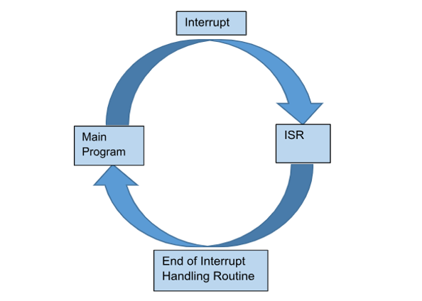
What is an Interrupt
The interrupt is used to pause the execution of a program in the loop() function to execute another function or command for a small interval of time. They sequence the execution of programs. They are used for the calculation of time during events and the generation of sampling frequency.
What is a Pre-Scalar
A pre-scalar is a digital circuit module that divides input clock frequency by a certain number to control the clock rate. The pre-scalar divides the pulses by a user-defined number that can be 1, 8, 62, or 256. The advantage of using a pre-scalar is that it can control the speed of the timer.
Arduino Timer Interruptions Through ISR (Interrupt Service Routine Function)
ISR, also known as an interrupt handler, uses the attachInterrupt() function to generate an interrupt signal.
Syntax
The attachInterrupt() function takes three different parameters for generating the interrupt signal. Given below is the syntax of the attachInterrupt() function and its parameters are explained below one by one.
Parameters
This function takes three parameters.
- digitalPinToInterrupt(pin) will indicate the interrupt number. Arduino UNO has two interrupt pins 2 and 3. They are attached to interrupts 0 and 1 respectively. So, you need to write 2 or 3 in place of a pin depending on your hardware design.
- ISR is to call an Interrupt Service Routine function that allows an interrupt to occur.
- Mode will decide when an interrupt should be invoked.
Modes of Interrupt
An interrupt has different modes LOW, RISING, FALLING, CHANGE. These modes are described below:
- LOW is stimulated when the interrupt pin is low.
- RISING is stimulated when the transition from LOW to HIGH occurs in the signal.
- FALLING is stimulated when the transition from HIGH to LOW occurs in the signal.
- CHANGE is invoked when a transition from HIGH to LOW or LOW to HIGH is observed in a signal.
There can be multiple functions that are performed using interrupt signals. These are comparison, overflow, and input capture which are explained below:
1. Comparison
This function is performed by Compare, Match interrupt. We can save our desired value in a register and when the timer reaches that value, an interrupt signal is generated. It is available in all three timers.
2. Overflow
An overflow interrupt is generated when a timer has reached its maximum value. This interrupt is also available in all three timers.
3. Input Capture
This interruption is generated whenever an external signal is applied. It captures the timestamp in the memory of the Arduino as long as an external or input signal is received. It is only available in Timer 1.
Using Timer1 Interrupt to Make a Blinking LED Every Second on Arduino UNO
Step 1
To create a blinking LED every second using Timer1 interrupt, you need to copy and paste the code given below:
#include <avr/interrupt.h>
const int LED_pin = 13;
unsigned int reload = 0xF424;
volatile int count;
ISR(TIMER1_COMPA_vect) {
count++;
flash();
}
void setup() {
Serial.begin(115200);
pinMode(LED_pin, OUTPUT);
digitalWrite(LED_pin, LOW);
cli();
TCCR1A = 0;
TCCR1B = 0;
OCR1A = reload;
TCCR1B = (1 << WGM12) | (1 << CS12);
TIMSK1 = (1 << OCIE1A);
sei();
Serial.println("TIMER1 Setup Finished.");
}
void loop() {
Serial.println(count); // you can add what you want to print
delay(1000);
}
void flash() {
static boolean output = HIGH;
digitalWrite(LED_pin, output);
output = !output;
}
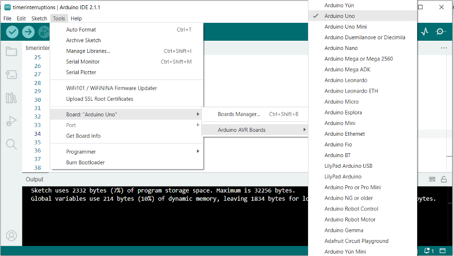
Step 2
After successfully pasting the code, connect Arduino UNO to your device through the Arduino cable. Select Arduino UNO by going to Tools> Board>Arduino AVR Boards>Arduino UNO and also select the port that is available below the Board option as shown below. Upload the code in Arduino by clicking on the arrow button that is pointing right.
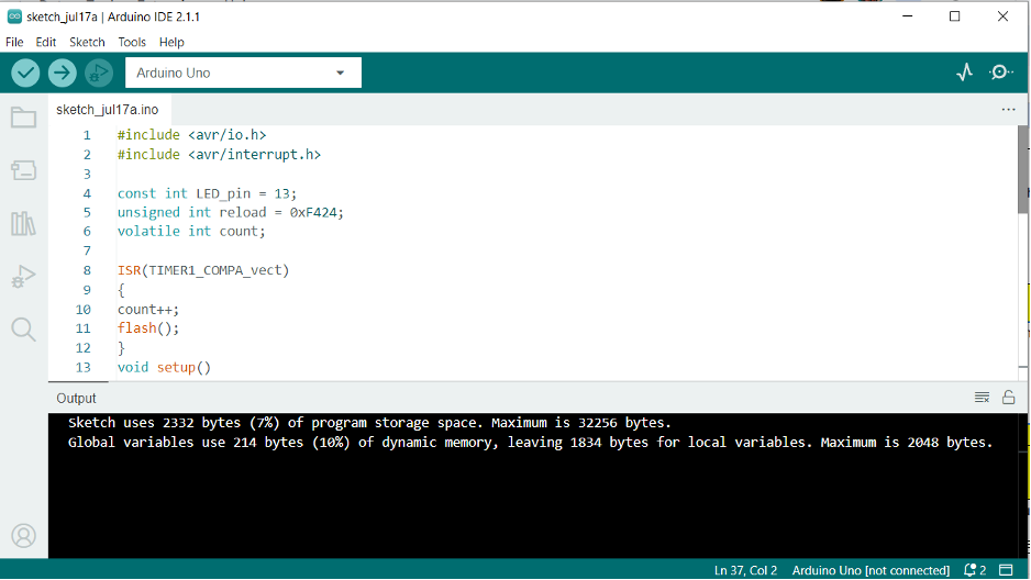
Step 3
When Code is uploaded in Arduino, click on the tick sign to run the program. The following output will appear.
Now open the Serial Monitor from the tools section and select the Baud rate of 115200. The serial monitor will show the following output.
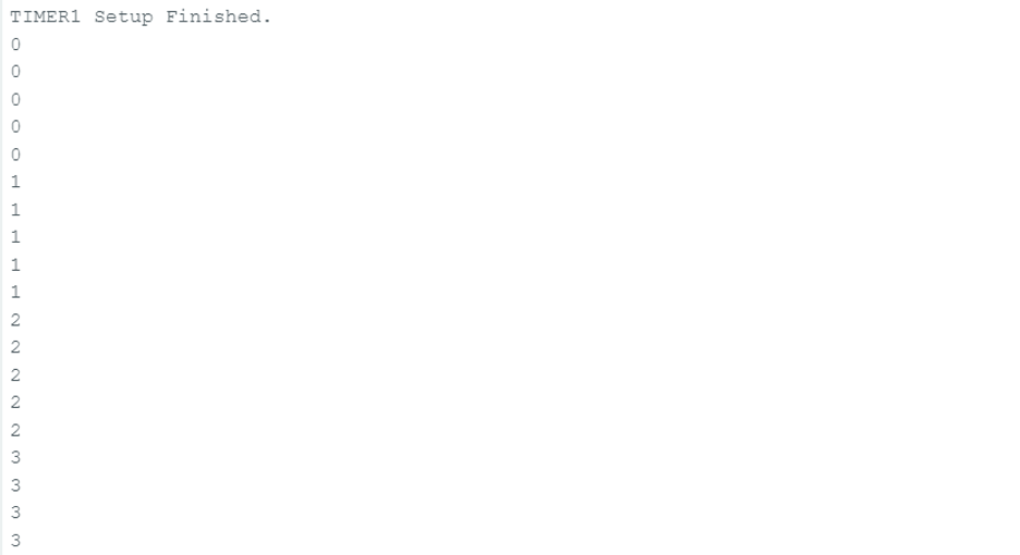
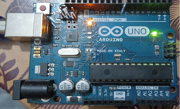
On the Arduino UNO, you will observe the LED blinking after every second. In the picture below, you can see the orange LED glowing.
Conclusion
Arduino timer interruptions are performed through an interrupt handler or interrupt service routine function. The interrupt handler uses attachinterrupt() to generate an interrupt when required. Timers are used in hardware to generate multiple kinds of interrupts such as compare, match, and overflow.