
How Does Arduino Relay Work?
Arduino relays operate using the electromagnet principle. When a digital signal from the Arduino is sent to the relay, the electromagnet inside the relay is energized, causing the contacts to close or open. This, in turn, allows or interrupts the flow of electrical current to the connected device.
Relay Pinout
A power relay module functions as an electrical switch triggered by a low-power signal from microcontrollers like ESP32 and Arduino. It can control high voltage appliances that are working over 120-220V. By utilizing the control signal from the microcontroller, we can easily turn these appliances ON or OFF.
Typically, a single-channel relay module consists of six pins.
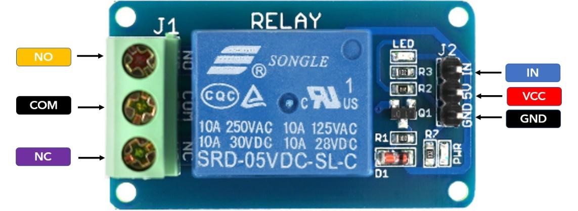
The six pins include:
| Pin | Pin Name | Description |
|---|---|---|
| 1 | Relay Trigger Pin | This pin is used as the input for activating the relay. |
| 2 | GND | It serves as the reference ground for the circuit. |
| 3 | VCC | This pin is the input supply for the relay coil. |
| 4 | NO | It is the terminal that remains open by default but closes when the relay is activated. |
| 5 | Common | This terminal is common to both the Normally Open and Normally Closed terminals. |
| 6 | NC | By default, this terminal is closed and breaks the connection when the relay is activated. |
Types of Relays
Relay modules are available in various types based on the number of channels they possess. These modules can be found with 1, 2, 3, 4, 8, and even 16 channels, determining the number of devices that can be controlled through their output terminals.
Let’s briefly compare the specifications of single-channel, dual-channel, and 8-channel relay modules.
| Specification | 1-Channel Relay | 2-Channel Relay | 8-Channel Relay |
|---|---|---|---|
| Supply Voltage | 3.75V-6V | 3.75V-6V | 3.75V-6V |
| Trigger Current | 2mA | 5mA | 5mA |
| Current Active Relay | 70mA | Single(70mA) Dual (140mA) | Single(70mA) All 8 (600mA) |
| Max Contact Voltage | 250VAC or 30VDC | 250VAC or 30VDC | 250VAC or 30VDC |
| Minimum Current | 10A | 10A | 10A |
Dual Channel Relay Pinout
The dual-channel relay module consists of:
- Mains Voltage Connections
- Control Pins
- Power Supply Selection
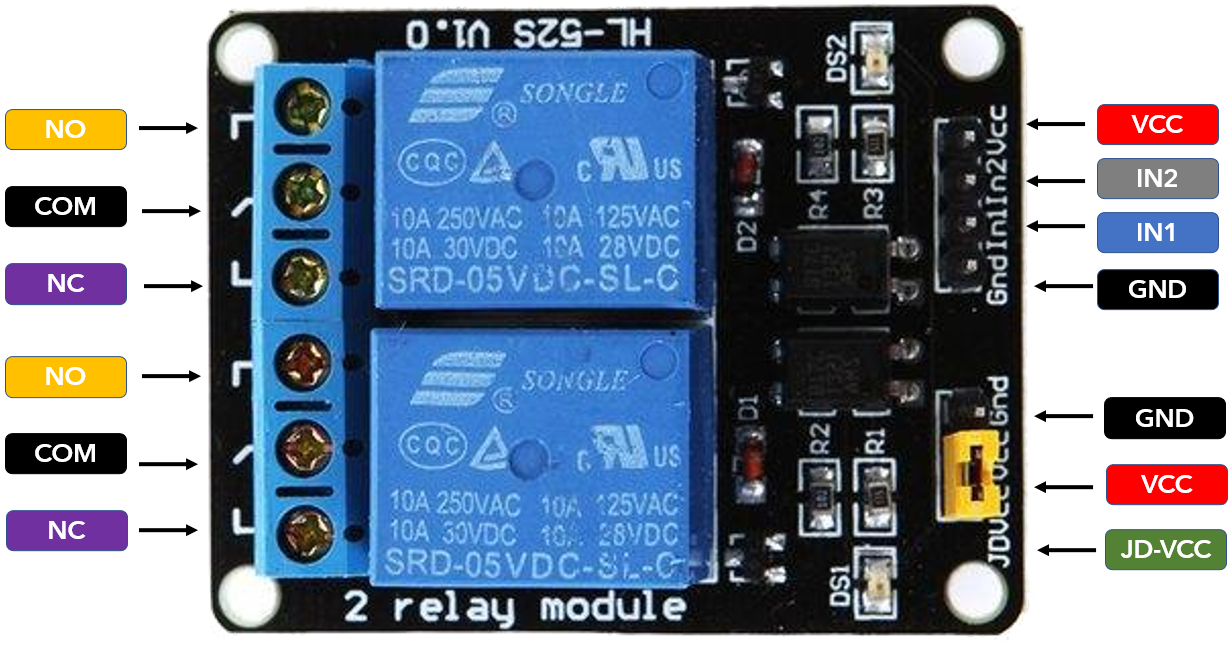
Main Voltage Connections
Inside the dual-channel relay module, there are two separate connectors for main voltage connections. Each connection consists of three pins:
- Normally Open (NO)
- Normally Closed (NC)
- Common.
The Common pin manages the flow of electricity in the external device. By default, the current flows between the Common and NC pins, creating a complete circuit.
However, when a trigger signal is received, the circuit opens, interrupting the current flow.
On the other hand, in the Normally Open configuration, there is no current flow by default. The current only starts flowing when a trigger signal is given by the microcontroller.
Control Pins
The other side of the relay module includes two sets of pins: one set with four pins and the other set with three pins. The first set, which operates at low voltage, consists of VCC, GND, IN1, and IN2 pins. In the relay module, we have separate IN pins for each relay.
The IN pin is where the control signal is sent by the microcontroller. If the IN pin in the relay gets a voltage signal of less than 2V, it will trigger the relay module. We can set different configurations depending on project needs:
Normally Closed Configuration:
- 1 or HIGH: Current starts flowing.
- 0 or LOW: Current stops flowing.
Normally Open Configuration:
- 1 or HIGH: Current stops flowing.
- 0 or LOW: Current starts flowing.
Power Supply Selection
We have another set of pins that are VCC, GND, and JD-VCC. Normally, the JD-VCC pin is connected to
- The JD-VCC pin is normally connected to VCC, so the relay is powered by the microcontroller.
- By removing the jumper connector cap from the JD pin a separate source of power is required for the relay module.
In other words, the JD-VCC pin is a jumper that allows you to choose whether to power the relay module from the microcontroller or a separate power source. If you leave the jumper connected, the relay module will be powered by the microcontroller. In case we remove the jumper, a separate voltage is needed for the relay module itself so it can be powered using an external source.
Conclusion
Arduino relays are the components used for controlling high-power devices using the Arduino microcontroller. They provide a safe and efficient means of automating various systems, ranging from home appliances to industrial machinery. By understanding the basics of Arduino relays and their applications, we can easily control AC or DC appliances inside Arduino projects. Read more about Arduino relay in this article.