Input/output functions
There are five different types of functions that are used in Arduino for configuring its inputs and outputs. The following input output functions are briefly discussed in this discourse:
- pinMode() function
- digitalRead() function
- digitalWrite() function
- analogRead() function
- analogWrite() function
pinMode() function
For connecting the peripherals to the Arduino board its pins are assigned to each device that has to be connected to the Arduino board. The pin number is assigned in the Arduino code using the pin mode function. The pin mode function has two arguments: one is the pin number, and the other is the mode of the pin. The pin modes are further divided into three types.
- INPUT
- OUTPUT
- INPUT_PULLUP
INPUT : It defines the respective pin that will be used as an input for Arduino.
OUTPUT : This mode is used when instruction is to be given to any connected device.
INPUT_PULLUP : This mode is also used to assign input state to the pin. By using this mode the polarity will be reversed of the given input for example if the Input is high that will mean the device is off and if the input is low that means the device is on. This function works with the help of internal resistors that are built in Arduino.
Syntax : To use the pin mode, function the following syntax should be followed:
digitalRead() and digitalWrite() functions
There are 14 digital pins in the Arduino Uno which can be used for the read and write functions. When the status of any specific pin is to be known then the digitalRead() function is used. This function is a return type function as it will tell the status of the pin in its output.
Similarly, when a state is to be assigned to any pin then a digitalWrite() function is used. The digitalWrite() function has two arguments one is the pin number and other is the state that will be defined by the user.
Both functions are of Boolean type so, only two types of states are used in digital write function one is high and the other is low. To use digitalRead() and digitalWrite() functions the following syntax should be used:
digitalWrite(pin-number , state);
Example
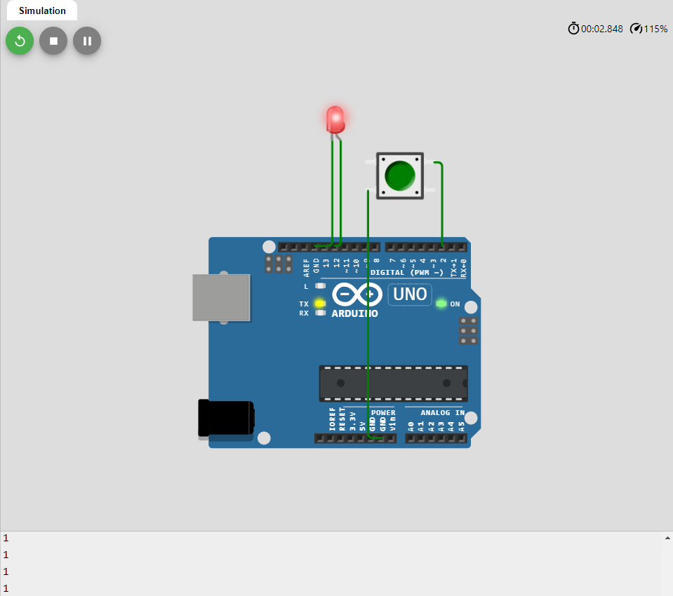
In the below mentioned example, pinMode(), digitalRead() and digitalWrite() functions are used:
int ledPin = 12;
// variables will change:
int buttonState;
void setup() {
Serial.begin(9600);
pinMode(ledPin, OUTPUT);
pinMode(buttonPin, INPUT_PULLUP);
}
void loop() {
buttonState = digitalRead(buttonPin);
Serial.println(buttonState);
if (buttonState == 1) {
// turn LED on:
digitalWrite(ledPin, 1);
} else {
// turn LED off:
digitalWrite(ledPin, 0);
}
}
In the example code a led is made turned on and off using the input and output functions and also a push button is used.
First the pin number for the button and the LED is declared and the INPUT_PULLUP is given to the button as its mode and then the LED is given the output as its mode.
To read the state of the button it must be in the input mode that’s why INPUT_PULLUP is given to the button and in the setup function using the pin mode the declared pins are assigned to Arduino for both button and led.
Similarly, after that the loop reads the initial state of the button by using the digitaRead () function.If the state of the button is high then the LED will be given the state high which means that LED will turn on. However, if the state of the button is Low then the state of LED will be Low that means the LED will turn off.
Since the INPUT_PULLUP is used for a button which inverts the inputs of the button like change High Into low and vice versa. So, when the program is compiled the LED will also turn on and upon pressing of the button the LED will turn off.
Output
analogRead() and analogWrite() functions
The Arduino Uno has 6 analog ports which can be used by these analog read and write functions. The analogRead() function will read the state of the analog pin and will return a value in the form of numbers in the range from 0 to 1024 for 10 bits resolution and for 12 bits resolution the range will be 0 to 4095.
The bit resolution is the analog to digital conversion so for 10 bit the range can be calculated by 2^10 and for 12 bits it will be 2^12 respectively. However, to assign a state to any analog pin on the Arduino Uno the function analogWrite() is used. It will generate the pulse modulation wave and the state will be defined by giving its duty cycle that ranges from 0 to 255.
The main difference between the analog and digital functions is that the digital defines the data in the form of either high or low whereas the analog gives the data in the form of a duty cycle of pulse width modulation. The syntax of the analogue read and write is given and after that an example code is given for illustration purposes:
analogWrite(pin-number , value-of-pin);
Example
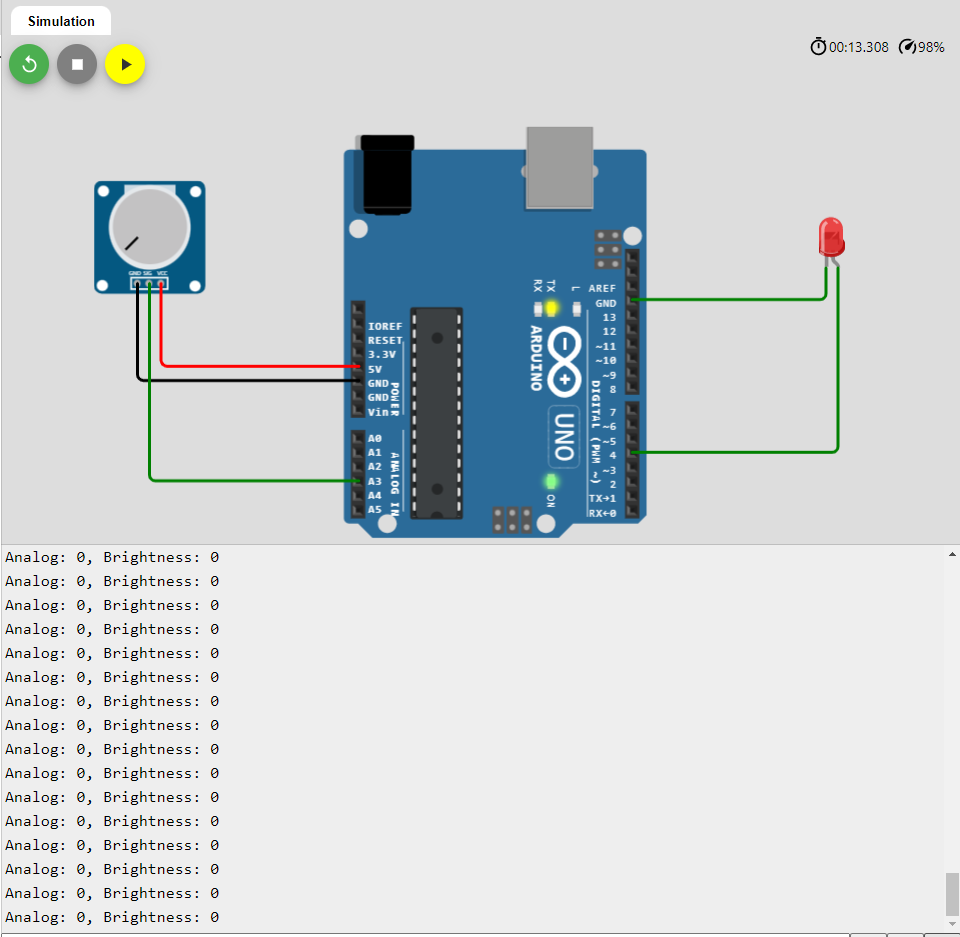
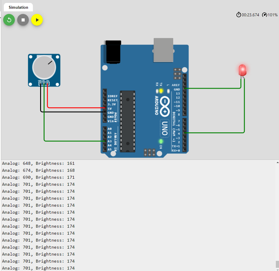
To demonstrate the use of digitalRead() and digitalWrite() functions an Arduino program for changing the brightness LED is compiled. The brightness of the LED is changed using the potentiometer which is connected to the analog pin A3 of the Arduino. The analogRead() function reads the output of the potentiometer and then the values of potentiometer are scalierized using the map function. After the value is scalierized it is given to the LED.
void setup() {
Serial.begin(9600);
pinMode(LED_PIN, OUTPUT);
}
void loop() {
int analogValue = analogRead(A3);
int brightness = map(analogValue, 0, 1023, 0, 255);
analogWrite(LED_PIN, brightness);
Serial.print("Analog: ");
Serial.print(analogValue);
Serial.print(", Brightness: ");
Serial.println(brightness);
delay(100);
}
When the value of the potentiometer is zero that means the resistance is maximum and there will be no voltage supplied to the LED. So, the value for the brightness will also be zero hence the LED will remain in off state.
When the value of the potentiometer is decreased the value of the brightness will increase and hence the LED will be in On state.
Conclusion
The input output functions play a very important part when it comes to interfacing devices with Arduino or when making hardware-based projects. These functions are building blocks of every Arduino project. In this write up the input output functions are discussed in detail with help of example codes.


