This article covers:
- What Is I2C Communication in Arduino
- I2C Pins in Arduino
- What Is I2C Wire Library
- Connecting Two Arduino Board Using I2C As Master and Slave
- Schematic
- Master Code
- Slave Code
- Output
- Conclusion
What Is I2C Communication in Arduino
I2C (Inter-Integrated Circuit) is a popular protocol for connecting microcontrollers with peripherals such as sensors and displays. Arduino UNO, a widely used microcontroller board, can be configured to communicate with other devices using I2C communication protocol.
Some main highlights of I2C communication include:
Multi-Master and Multi-Slave capability: I2C supports multiple master devices and multiple slave devices on a single bus, allowing for communication between multiple devices at the same time.
Low Pin Count: I2C uses only two lines, SDA and SCL, for communication, which reduces the number of required connections and simplifies wiring.
Addressable devices: Each I2C device on the bus has a unique address, allowing for easy identification and communication with specific devices.
High Speed: I2C is capable of high data rates of up to 3.4 Mbps, making it suitable for high-speed data transfer applications.
Power Saving: I2C allows for low-power communication between devices by allowing devices to be put into low power modes when not communicating and wake up on request.
I2C Pins in Arduino
In I2C communication, two lines are utilized:
- Data line (SDA): Data line for exchanging data between Master and Slave devices.
- Clock line (SCL): Clock line for synchronizing the I2C communication between devices.
The Master Arduino controls the I2C clock line and start the communication with peripherals, while the Slave devices respond to the master’s requests.
In the table below, you will find the pinouts of the I2C interface on various Arduino boards:
| Board | I2C Pins |
|---|---|
| Arduino Nano | SDA-A4 | SCL-A5 |
| Arduino Mega | SDA-A4 | SCL-A5 and SDA-20 | SCL-21 |
| Arduino Leonardo | SDA-A4 | SCL-A5 |
| Arduino Uno | SDA-A4 | SCL-A5 |
| Arduino Micro | SDA-02 | SCL-03* |
*I2C Pins may vary depending upon which board version you are using kindly see respective datasheet for more details.
What Is I2C Wire Library
The I2C Wire Library is preinstalled in an IDE that builds communication between I2C devices. The library contains functions for configuring and communicating on the I2C bus, including functions for initializing the bus as a Master or Slave device, sending, and receiving data, and controlling the clock speed.
The library makes it easy to communicate with I2C devices by abstracting away the low-level details of the I2C protocol and providing simple, high-level functions that can be used in Arduino sketches. For example, the begin() function is used to initialize the I2C bus as a Master or Slave device
The library also supports the use of multiple I2C buses, allowing for communication with multiple devices at the same time. If you are dealing with multiple sensors or displays for a project, this is helpful.
Connecting Two Arduino Board Using I2C As Master and Slave
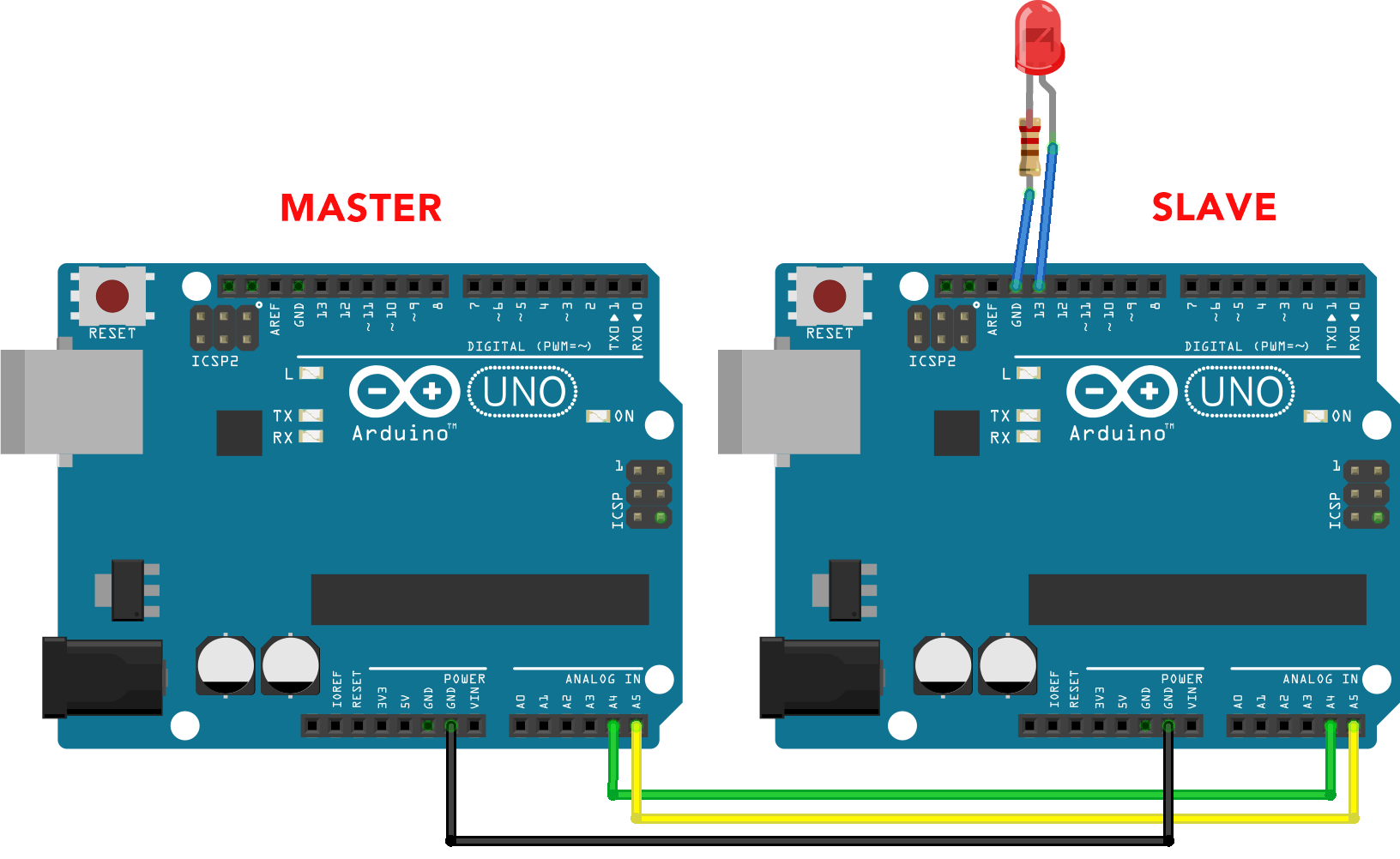
To establish I2C communication between two Arduino UNO boards, the SDA and SCL pins of both boards must be connected together and share a common ground. The communication can be achieved by using the inbuilt Wire library in Arduino which contains functions for configuring and communicating on the I2C bus.
Schematic
Below image shows two Arduino Uno boards connected in Master-Slave configuration:
Master Code
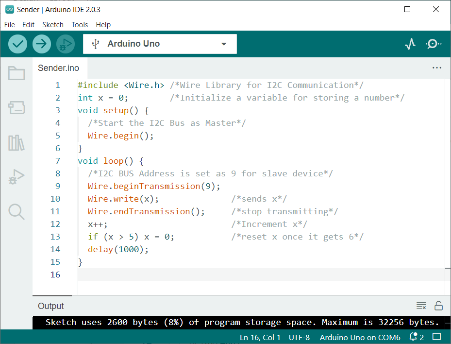
Upload below code to Master Arduino board:
int x = 0; /*Initialize a variable for storing a number*/
void setup() {
/*Start the I2C Bus as Master*/
Wire.begin();
}
void loop() {
/*I2C BUS Address is set as 9 for Slave device*/
Wire.beginTransmission(9);
Wire.write(x); /*sends x*/
Wire.endTransmission(); /*stop transmitting*/
x++; /*Increment x*/
if (x > 5) x = 0; /*reset x once it gets 6*/
delay(1000);
}
Code started by includes the I2C Master library. A variable is initialized that will store the integer values starting from 0 to 5. The I2C address for the Slave device is defined as 9. Using the Wire library function
On the Master board, the begin() function will initialize the I2C bus as a Master device
Once the boards are configured, they can communicate with one another over the I2C bus. The Master Arduino request data from Slave Arduino board and the Slave can respond with the requested data.
Slave Code
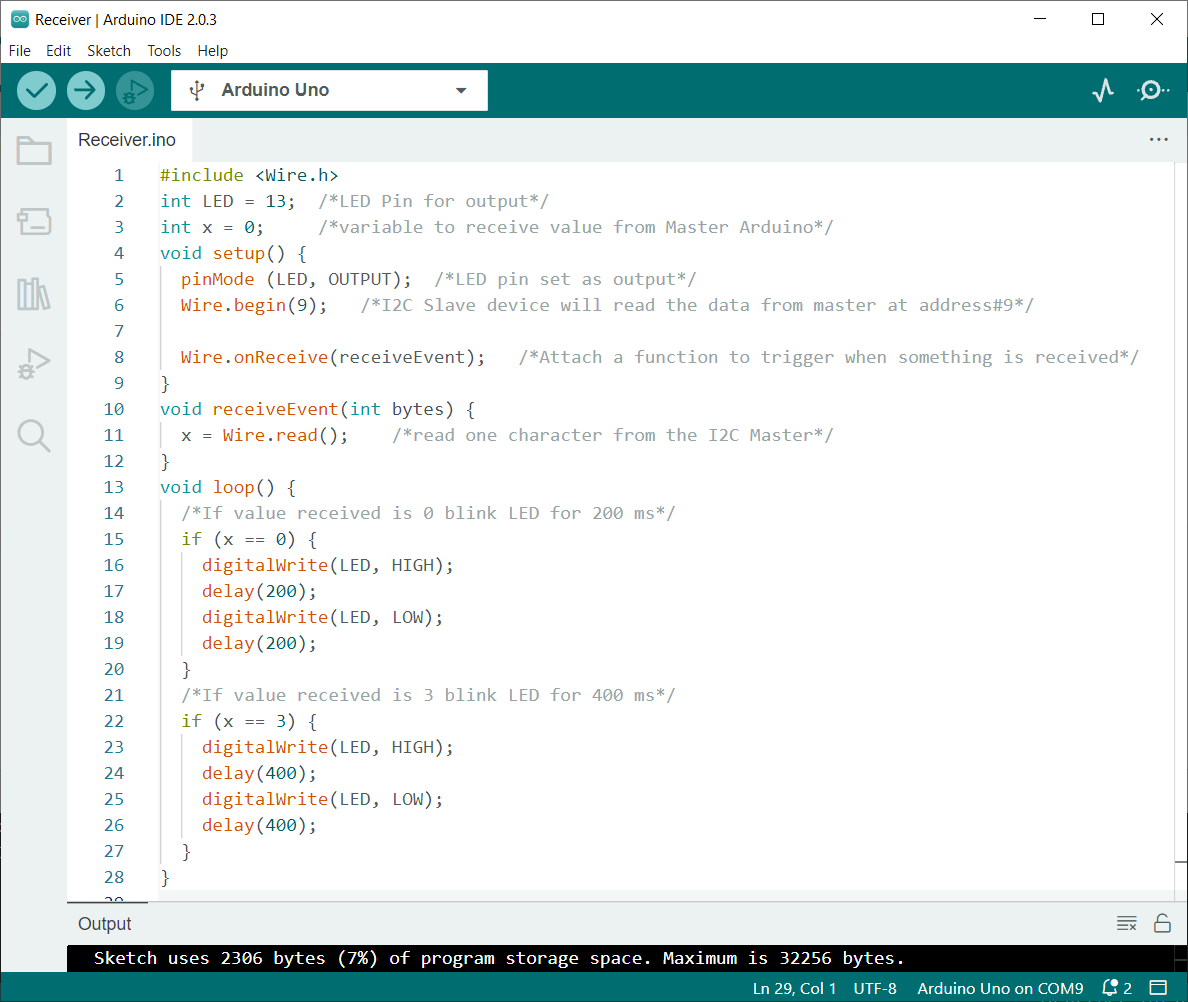
Upload below code to Slave Arduino board at which LED is connected:
int LED = 13; /*LED Pin for output*/
int x = 0; /*variable to receive value from Master Arduino*/
void setup() {
pinMode (LED, OUTPUT); /*LED pin set as output*/
Wire.begin(9); /*I2C Slave device will read the data from Master at address#9*/
Wire.onReceive(receiveEvent); /*Attach a function to trigger when something is received*/
}
void receiveEvent(int bytes) {
x = Wire.read(); /*read one character from the I2C Master*/
}
void loop() {
/*If value received is 0 blink LED for 200 ms*/
if (x == 0) {
digitalWrite(LED, HIGH);
delay(200);
digitalWrite(LED, LOW);
delay(200);
}
/*If value received is 3 blink LED for 400 ms*/
if (x == 3) {
digitalWrite(LED, HIGH);
delay(400);
digitalWrite(LED, LOW);
delay(400);
}
}
Code started by including Wire library and next we set the built in LED at pin 13 of Slave Arduino as output. Next a variable x is defined that will receive data from the Master Arduino. Using this integer value, we will blink LED at a particular character once it is received.
In loop(), the received character is then translated into a different speed of LED blinking depending on the character received. If the condition is used when the received character from the Master device is 0 the LED will blink with 200ms and if the received character IS 3 LED will blink with delay of 400ms.
In case of any other characters LED will remain OFF.
Output
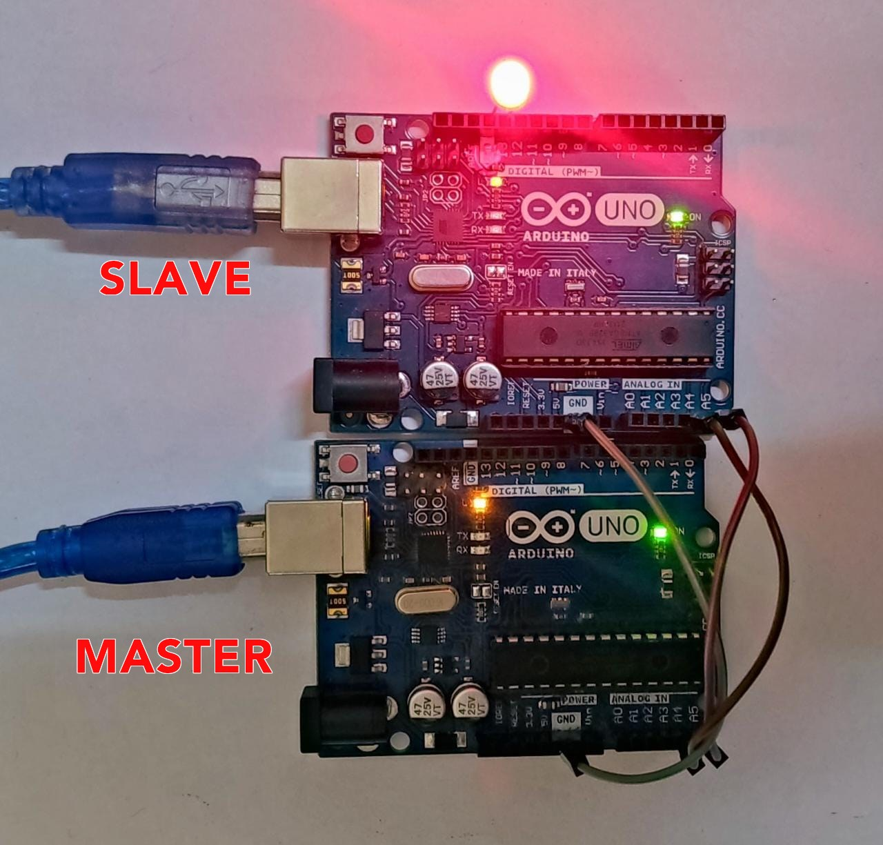
In output we can see LED connected with Slave Arduino blinks every time Master sends a character 0 or 3.
Conclusion
I2C communication allows multiple devices to communicate with each other using a common bus. Arduino boards can be configured to communicate with one another using I2C by connecting the SDA and SCL pins and configuring the boards as Master and Slave using the Wire library in Arduino. Using I2C multiple-device communication within a project is therefore easier and more efficient.


