The ADC(analog to digital converter) is a technique by which we can convert analog values to digital values. Why do we need this conversion of analog to digital and also what is the difference between analog and digital values? The values which have only two possible states either one or zero are known as binary values like the output of a push-button; either it will be open (zero) or closed (1). Contrary to it, some values are continuous like the frequency of human sounds, it generates the continuous sound wave which has different values, such values are known as analog values.
The machines understand only binary values which are in the combination of zeros and ones, whereas the digital values are representations of the binary numbers. In this write-up, the utilization of ADCs in Arduino is discussed, and also its process of conversion is explained.
What are the ADCs in Arduino
In Arduino, different sensors and electrical components are connected which input the analog signals whereas Arduino can understand only digital signals. To resolve this, every board of Arduino has some built-in ADCs which convert the analog input into digital values which are readable by Arduino. We will discuss the ADCsof Arduino Uno, it has 6 pins to take the input which are denoted by A0, A1, A2, A3, A4, and A5.
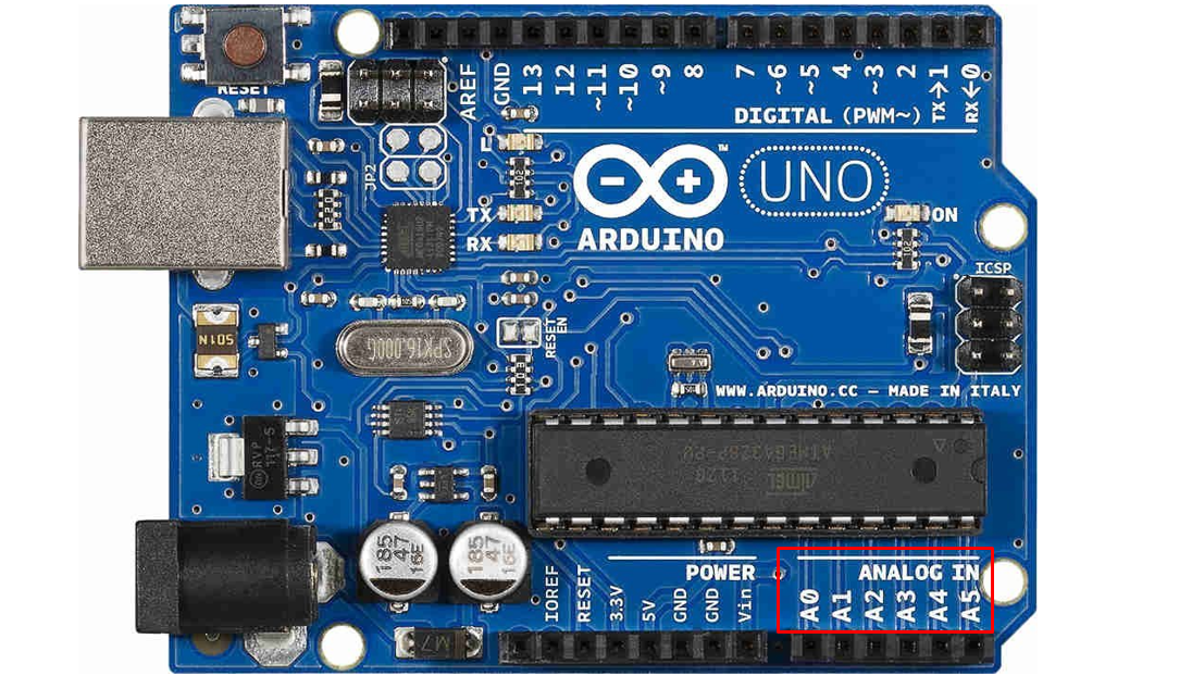
These six pins have the 10-bit ADC so they will convert the analog values into digital values in the range of 0 to 1023 and this value is known as the resolution because it represents the discrete values.
How the ADCs works in Arduino
In Arduino, the analog values are mapped to the digital values by the factor of 5mV (this value of 5mv comes by dividing the Vref value to 1023), which means it will increase the digital value by one on the increase of every 5 mv analog value.
Consider the following table for a better understanding:
| Analog value | Value in bits | Digital value |
|---|---|---|
| 0 volts | 0000000000 | 0 |
| 5 mv | 0000000001 | 1 |
| 10 mv | 0000000010 | 2 |
| 5 volt | 1111111111 | 1023 |
What is the analog to digital formula
There is a mathematical equation by which we can convert the analog values into digital values and the formula is:
To understand the above equation consider the following values to find out the ADC reading:
Input voltage= 10 volts
ADC reading= x (it is to find)
Analog measured value= 3 volts (assume the sensor is reading the value of 3 volts)
According to the above equation:
So the digital value which is read by Arduino against the analog value of 3 volts will be 614.
To understand it, we will configure the circuit using the potentiometer, in which we will vary the analog input voltage, then will display the analog and digital values on the serial monitor. The Arduino code for this purpose will be:
float a_value=0.00;
void setup() {
Serial.begin(9600);
}
void loop() {
d_value= analogRead(potpin);
Serial.print("Digital value = ");
Serial.print(d_value);
a_value= (d_value * 5.00)/1023.00;
Serial.print(" analog voltage = ");
Serial.println(a_value);
delay(1000);
}
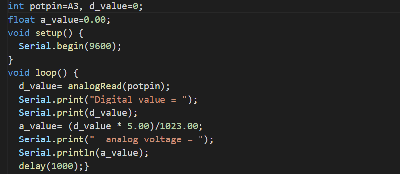
Explanation of code: We have declared two integers variables potpin with value A3(potentiometer will be connected on pin A3) and d_value with 0 value. A variable of float data type that is a_value and stores zero in it. In the loop, we are reading the values of a potentiometer and saving its values in the d_value variable. Then using the mathematical formula explained above, convert the d_value into analog and store it in the variable a_variable. We displayed both values on the serial monitor through the serial communication and produced a delay of 1 second in every iteration of the loop.
Hardware and Simulation
We will need the following components:
- A potentiometer of 4.7k ohm
- Arduino Uno
- Breadboard
- Connecting wires
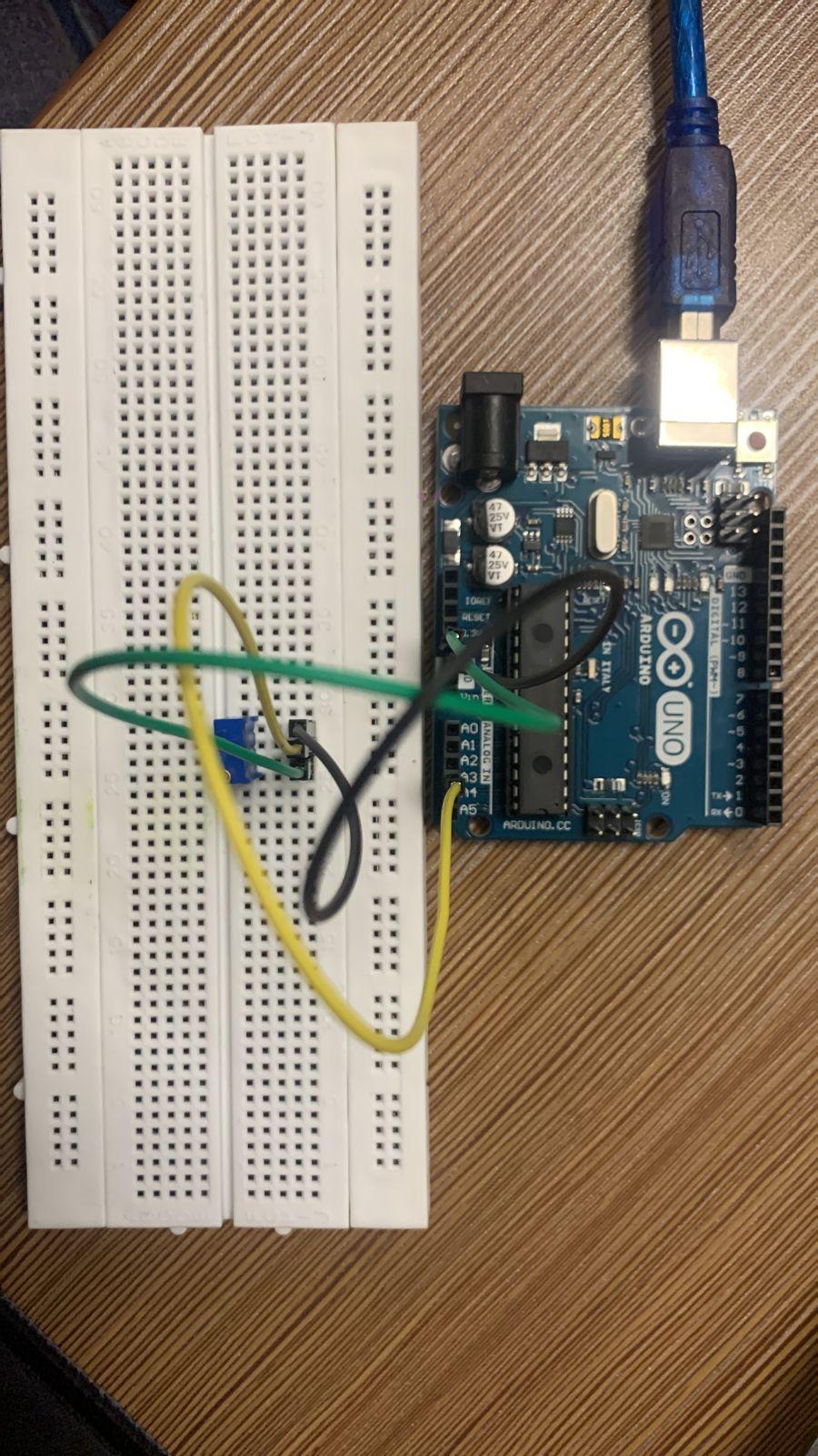
Connect the one leg of the potentiometer with the ground, the other leg with 5 volts, and the middle leg with the analog channel of A3. The circuit diagram of the circuit of potentiometer with Arduino will be:
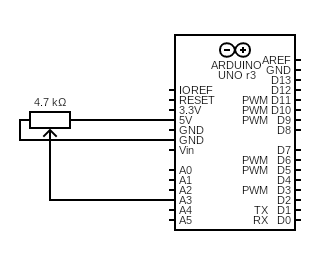
In the above circuit, as we change the values of an analog pin, we can visualize the corresponding digital values on a serial monitor. The real-time simulation of the above circuit will be:
The hardware configuration will be like this:
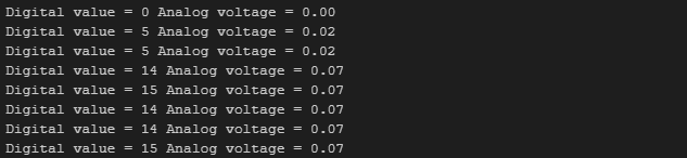
The serial monitor output will like this on varying the resistance of the potentiometer:
Conclusion
The ADCs in Arduino are used for the conversion of analog input values into digital values because the analog values cannot be processed by Arduino; machines and microcontrollers because they only understand the digital values. In this write-up, the ADCs are explained with their working in Arduino and also demonstrated an example of working of ADC in Arduino.