In the modern electronic world timing circuits are very important. The same is the case with Arduino, Arduino has a built-in timer clock that counts to approximately 49 days but after that it resets. Secondly, the Arduino internal clock is not 100% accurate; there is always a certain percentage of time lag between Arduino clock and an external clock. So, if one wants to create an accurate clock using Arduino, we must rely upon an external module known as RTC (Real Time Clock). Let’s see how to interface this RTC module with Arduino and create an accurate digital clock.
RTC Module with Arduino
Sometimes working on Arduino projects need an accurate time clock to keep Arduino working and execute special instructions and commands on some specific time. Arduino have in-built clock however we cannot rely on it because of following two reasons:
-
- The Arduino clock is inaccurate with a percentage error of 0.5-1%.
- The Arduino clock will reset automatically once the board is reset.
- Arduino clocks have no power backup if Arduino loses power its clock will reset automatically.
Considering the above-mentioned reasons, users prefer using an external hardware clock or an RTC module. So, one very cheap and super accurate module widely used is DS1307. Let’s see how to connect this RTC with Arduino.
Setup RTC Module Arduino Library
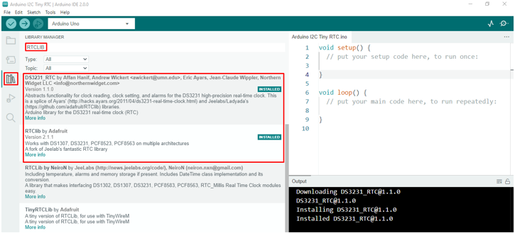
To interface Arduino with the RTC module we need to install some necessary libraries that can read data from the RTC module. Follow the steps to install RTC libraries:
-
- Open IDE
- Go to Library section
- Search “RTCLIB”
- Install the DS3231_RTC and RTClib by Adafruit.
DS1307 RTC Module
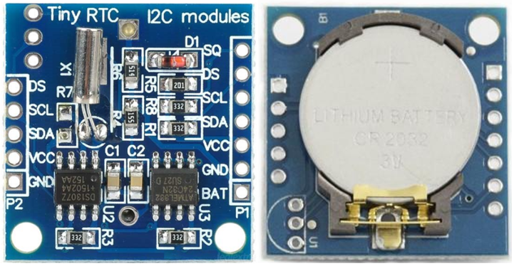
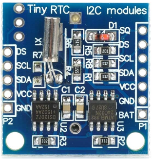
The DS1307 RTC module is based upon the tiny Clock chip DS1307 which also supports I2C communication protocol. On the back side of the RTC module we have a lithium cell battery. This module can give accurate information of seconds, minutes, hours, day, date, month and year. It also has the capability of automatic time adjustment for 31 days a month along with leap year error support. Clock can either operate in 12 hour or 24-hour clock time.
Some main highlights of this RTC module:
-
- Can work on 5V DC supply
- Square wave output that can be programmed
- Power failure detection
- Consume very less amount of current (500mA)
- 56-Byte non-volatile RAM
- Battery backup
Pinout of RTC Module
| Pin Name | Description |
| SCL | Clock input pin for I2C communication interface |
| SDA | Data input output for I2C serial communication |
| VCC | Power Pin range from 3.3V to 5V |
| GND | GND Pin |
| DS | Use for temperature sensor input |
| SQW | This pin can generate four square waves with frequency 1Hz, 4kHz, 8kHz or 32kHz |
| BAT | Pin for battery backup if main supply interrupted |
Circuit Diagram
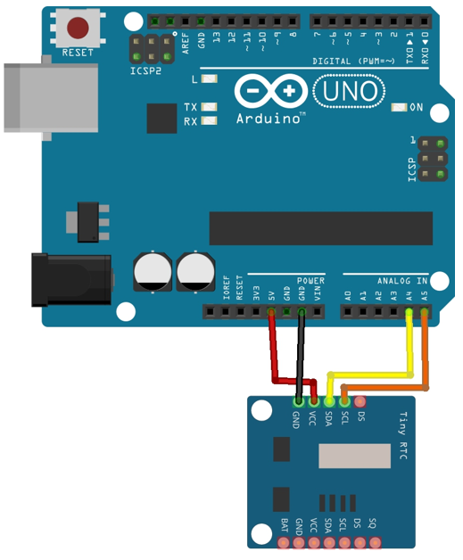
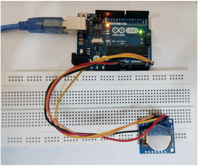
Connect the Arduino board with the RTC module as shown in diagram below. Here A4 and A5 pins of Arduino will be used for I2C communication with RTC modules while 5V and GND pins will give the required power to the RTC module.
| DS 1307 RTC Pin | Arduino Pin |
| Vin | 5V |
| GND | GND |
| SDA | A4 |
| SCL | A5 |
Code
#include <Wire.h>
RTC_DS3231 real_time_clock;
char time[32]; /*Char array is defined*/
void setup()
{
Serial.begin(9600); /*Serial communication begins*/
Wire.begin(); /*Library file to begin communication*/
real_time_clock.begin();
real_time_clock.adjust(DateTime(F(__DATE__),F(__TIME__)));
/*real_time_clock.adjust(DateTime(2022, 09, 26, 1, 58, 0))*/
}
void loop()
{
DateTime now = real_time_clock.now();
sprintf(time, "%02d:%02d:%02d %02d/%02d/%02d", now.hour(), now.minute(), now.second(), now.day(), now.month(), now.year());
Serial.print(F("Date/Time: ")); /*This will print date and time*/
Serial.println(time);
delay(1000); /*Delay of 1 sec*/
}
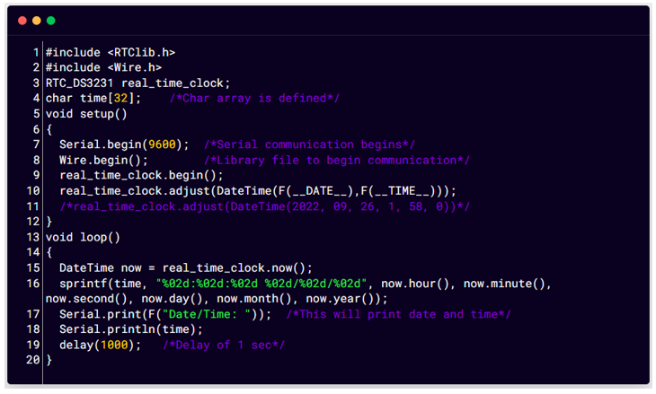
At the start of code first we included wire.h & RTClib for communication with devices. We then created an RTClib object with the name real_time_clock. Next, we defined a char array time of length 32, which will store date and time information.
In the setup and loop function we used the following command to make sure I2C communication is established between Arduino and RTC modules.
Wire.begin and real_time_clock.begin will ensure and check for RTC connection.
adjust() is an overloaded function which sets date and time.
This function will set the date and time at which sketch was compiled.
The now() functions return date and time, and its value will store in variable “time”.
Next hour, minute, second, day, month, year will calculate the exact date and print it on the serial monitor with a delay of 1 sec.
Hardware
Output
Serial monitor will start printing the time and date at which code is uploaded to the Arduino board.
Conclusion
Arduino itself has some functions related to time like millis(), micros(). However, these functions don’t give exact time; there is always a chance of some milliseconds delay. To avoid this while using Arduino RTC external modules are used. These modules such as DS1307 give us exact time with a battery backup that can last for many years. This guide covers how to interface these RTC modules with an Arduino board.

