DC Motor Control with Arduino
A DC motor is one of the widely used types of motor. It comes with two leads, one positive and second one negative. If we connect these two leads with a battery or power source, the motor will start rotating; however, if we reverse the polarity of the terminal motor will start rotating in the opposite direction.
Using Arduino, we can control motor speed and direction in a more flexible way. To control the motor with Arduino we use a motor driver module. A motor driver module is an external circuit that can interface an Arduino with any of the DC motors.
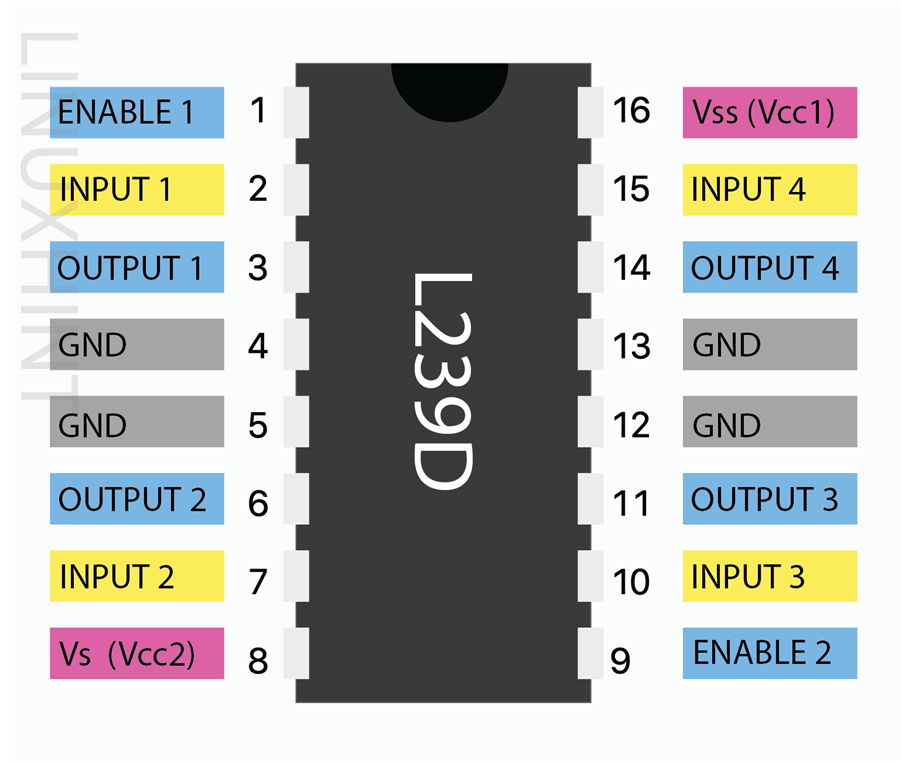
Here we will use the LN293D IC motor driver module to control a DC motor direction and speed. LN293D is a 16-pin motor driver module that can control two dc motors simultaneously. It can drive a motor with current up to 600mA per channel and voltage range start from 4.5 up to 36V (at pin 8). Using this driver module, we can control multiple small size DC motors.
Circuit Diagram
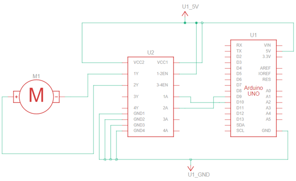
To control the DC motor, design the circuit according to the mentioned schematic. Connect pin 2 and 7 of the driver IC with the digital pin D10 and D9 of Arduino Uno respectively. Using digital pins, we will control the direction and speed of our motor. Pin 1 and 8 are given a high-level logic using Arduino 5V logic level voltage. The DC motor is connected at pin 3 and 6 of the driver module. Pin 4 and 5 are short because of common ground in the motor driver module.
Using pin 9 and 10 we can control motor direction. When pin 10 is high and pin 9 is low motor will rotates in one direction and to rotate in the opposite direction reverse conditions will be applied.
Schematics
Code
const int DCmotorSignal2 = 10; /*pin 10 for motor second input*/
void setup()
{
pinMode(DCmotorSignal1,OUTPUT); /*initialize the DCmotorSignal1 pin as output*/
pinMode(DCmotorSignal2,OUTPUT); /*initialize the DCmotorSignal2 pin as output*/
}
void loop()
{
clockwise(200); /*rotate in clockwise direction*/
delay(1000); /*delay of 1 second*/
anticlockwise(200); /*rotate in Anticlockwise direction*/
delay(1000); /*delay for 1 second*/
}
void clockwise(int rotationalSpeed) /*This function will drive and rotate motor in clockwise direction*/
{
analogWrite(DCmotorSignal1,rotationalSpeed); /*set motor speed*/
analogWrite(DCmotorSignal2,LOW); /*stop the DCmotorSignal2 pin of motor*/
}
void anticlockwise(int rotationalSpeed) /*The function will drive and rotate motor in Anticlockwise direction*/
{
analogWrite(DCmotorSignal1,LOW); /*stop the DCmotorSignal1 pin of motor*/
analogWrite(DCmotorSignal2,rotationalSpeed); /*set motor speed*/
}
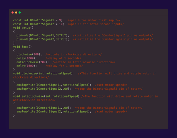
Here in the above code we initialize two digital pins for DC motor control. Digital pin 9 is set as input for the first pin and D10 is set as input for the second pin of the DC motor. Next using the pinMode function we initialize both these digital pins as output.
In the loop section of code two functions named clockwise and anticlockwise are initialized with a rotational speed of 200. After that using two void functions clockwise and anticlockwise we change the direction of motor rotation by setting pin 9 and 10 as LOW and HIGH.
Why We Used Motor Driver Module with Arduino?
Motor drivers can take a low current signal from an Arduino or any other microcontroller and increase it up into a high current signal that can drive any DC motor easily. Normally Arduino and other microcontrollers work on low current while to power DC motors they require high current constant input that Arduino cannot provide. Arduino can provide us with a maximum of 40mA of current per pin which is just a fraction of what a DC motor requires to operate. Motor driver modules like L293D can control two motors and provide users free hand to control speed and direction according to their ease.
Note: While using multiple motors with Arduino it is recommended to use external separate supply for DC motors along with motor driver module because Arduino cannot withhold current more than 20mA and normally motors take current a lot more than this. Another problem is kickback, stepper motors have magnetic components; they will continue to create electricity even when the power is cut off, which can lead to enough negative voltage that can damage the Arduino board. So, in short, a motor driver and separate power supply is necessary to run a DC motor.
Conclusion
DC motors are an important component for designing Arduino based robotics projects. Using DC motors Arduino can control motion and direction of project peripherals. To control these motors smoothly we need a driver module which not only saves the Arduino board from extreme current spikes but also gives complete control to the user. This article will guide you to design and interface DC motors in any Arduino project.


