This discourse explains the procedure for interfacing keypad with Arduino and displaying its input on the LCD.
Keypads
A Keypad is a small version of keyboard which can perform limited functions. These keypads are mostly used with the embedded systems where human and machine interaction is needed. For instance, when a passcode is required to open a door or to authorize any access.
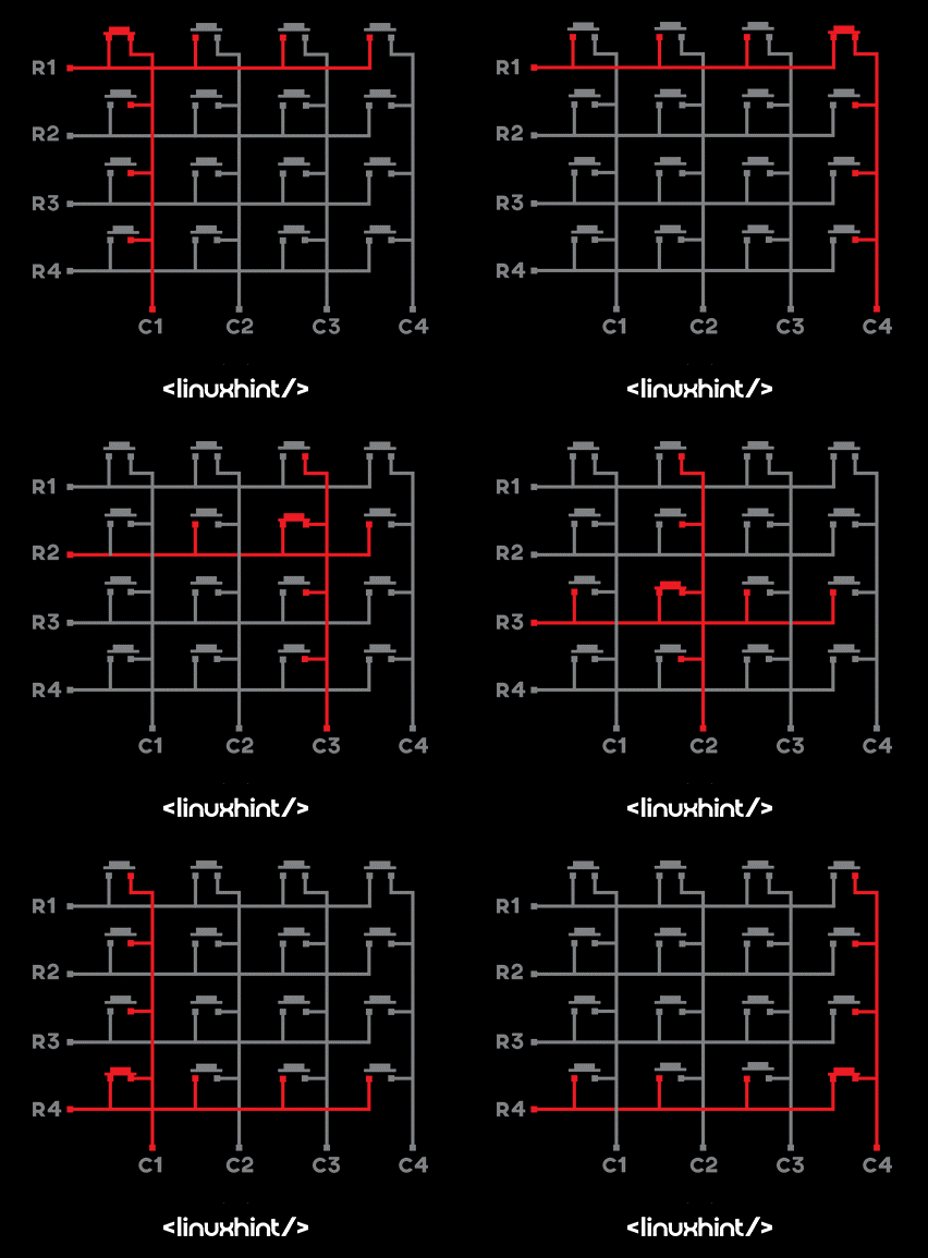
Similarly, the keypad is a viable option in the embedded systems as it requires a smaller number of pins and is compact in size. The most common size used for the keypad is 4×4 which has 4 columns and 4 rows and 8 pins in total.
The first four pins from the left side are the pins for the rows and the next 4 pins are the pins for the columns.
| Pins (From left to right) | Configuration |
|---|---|
| 1 to 4 | Rows of the keypad |
| 4 to 8 | Columns of the keypad |
The keys of the keypad are connected in such a way that the one pin of each key is common in the row and the other pin is common in the columns. All the pins of the keypad are taken as inputs by the Arduino and the microcontroller assigns the LOW state to rows and HIGH state to columns. Similarly, when a key is pressed the state of the columns is changed to LOW and in this way the Arduino finds out which key of the keypad is pressed.
Interfacing Keypad with Arduino and LCD
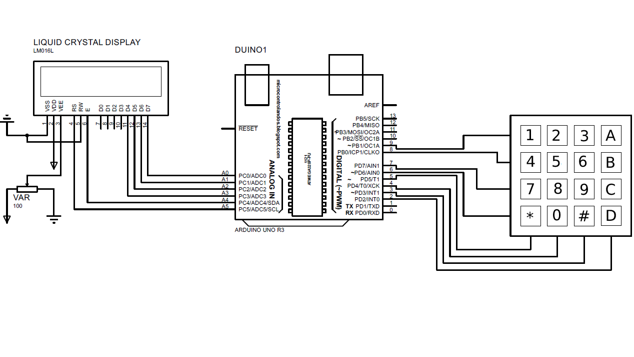
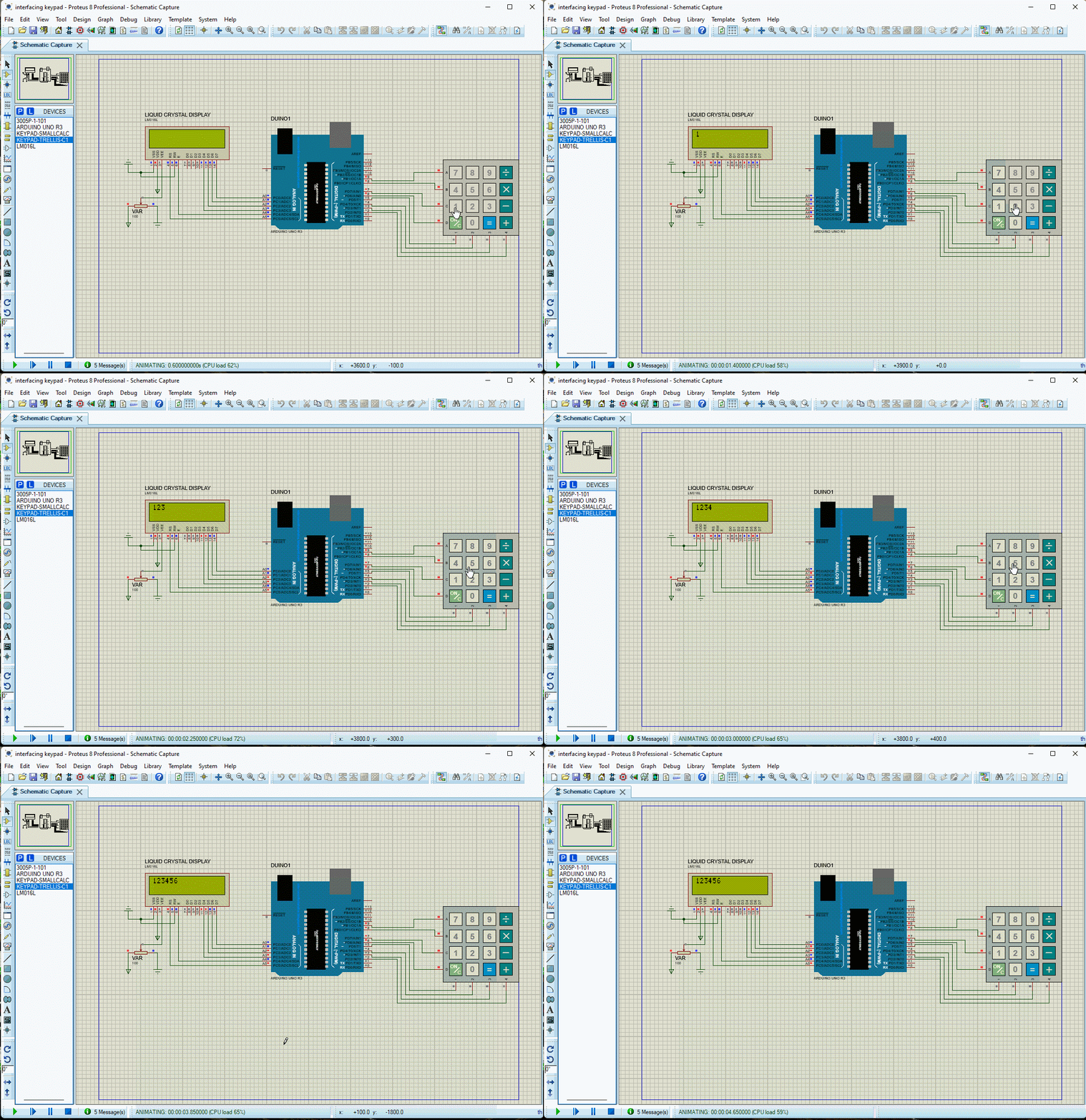
The schematic for the interfacing the keypad with Arduino and displaying the output at the liquid crystal display (LCD) is given as:
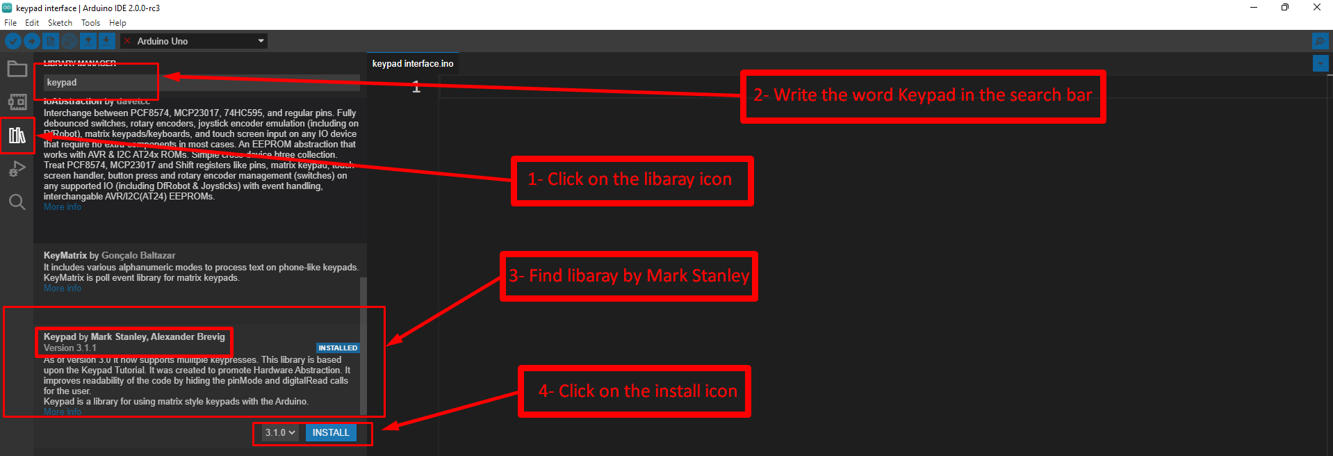
Below is the Arduino code for the interfacing of the keypad with Arduino Uno but first the library of the keypad is installed in the Arduino IDE by following the given procedure.
The syntax for defining the library for the keypad is:
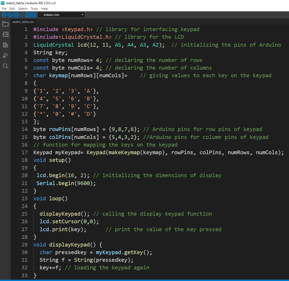
The code to interface keypad with Arduino is given as:
#include<LiquidCrystal.h> // library for the LCD
LiquidCrystal lcd(12, 11, A5, A4, A3, A2); // initializing the pins of Arduino
String key;
const byte numRows= 4; // declaring the number of rows
const byte numCols= 4; // declaring the number of columns
char keymap[numRows][numCols]= // giving values to each key on the keypad
{
{'1', '2', '3', 'A'},
{'4', '5', '6', 'B'},
{'7', '8', '9', 'C'},
{'*', '0', '#', 'D'}
};
byte rowPins[numRows] = {9,8,7,6}; // Arduino pins for row pins of keypad
byte colPins[numCols] = {5,4,3,2}; //Arduino pins for column pins of keypad
// function for mapping the keys on the keypad
Keypad myKeypad= Keypad(makeKeymap(keymap), rowPins, colPins, numRows, numCols);
void setup()
{
lcd.begin(16, 2); // initializing the dimensions of display
Serial.begin(9600);
}
void loop()
{
displayKeypad(); // calling the display keypad function
lcd.setCursor(0,0);
lcd.print(key); // print the value of the key pressed
}
void displayKeypad() {
char pressedkey = myKeypad.getKey();
String f = String(pressedkey);
key+=f; // loading the keypad again
}
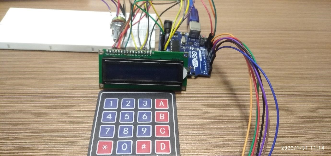
In the code the display module is connected to the analog pins of the Arduino and the keypad is initialized as a string.
The output of each button of the keypad is declared in the string and after that Arduino pins for the keypad are declared separately for rows and columns.
Furthermore, a function for the keypads is created which is called in the loop function when the button of the keypad is pressed.
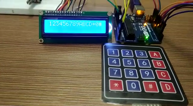
We can summarize the working of the program in such a way that when a key is pressed it is read by using the getkey() function and then it is printed on the display module using the lcd.print() function.
Output
Conclusion
When a human interface is required with any piece of machinery the keypad is used. Similarly, the keypad serves many functions in the projects where authorization is required. For example, like passcode entering, authorizing any instructions and these instructions or the inputs from the keypad can be displayed using the display modules. In this write-up a keypad is interfaced with Arduino and the input from the keypad are displayed on the LCD display.

