4: Interfacing Relay with ESP32
1: Introduction to Relays
Power relay module is an electromagnet switch controlled by a low power signal from microcontrollers such as ESP32 and Arduino. Using the control signal from the microcontroller we can turn ON or OFF the appliances that are even working on high voltages such as 120-220V.
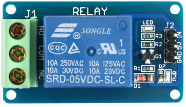
A single channel relay module normally contains 6 pins:
The six pins include:
| Pin | Pin Name | Description |
| 1 | Relay Trigger Pin | Input for relay activation |
| 2 | GND | Ground Pin |
| 3 | VCC | Input supply for relay coil |
| 4 | NO | Normally open terminal |
| 5 | Common | Common terminal |
| 6 | NC | Normally Closed terminal |
2: Types of Relays
Relay modules come in different variations depending upon the number of channels it has. We can easily find relay modules with 1, 2, 3, 4, 8 and even 16 channels relay modules. Each channel determines the number of devices we can control on the output terminal.
Here is a brief comparison of single, dual and 8 channel relay module specifications:
| Specification | 1-Channel Relay | 2-Channel Relay | 8-Channel Relay |
| Supply Voltage | 3.75V-6V | 3.75V-6V | 3.75V-6V |
| Trigger Current | 2mA | 5mA | 5mA |
| Current Active Relay | 70mA | Single(70mA) Dual (140mA) | Single(70mA) All 8 (600mA) |
| Max Contact Voltage | 250VAC or 30VDC | 250VAC or 30VDC | 250VAC or 30VDC |
| Minimum Current | 10A | 10A | 10A |
As we have covered a brief comparison between different channel relays now we will be using dual channel relay in this article for demonstration purposes.
3: Dual Channel Relay Pinout
Here in this article, we will be using dual channel relay. A dual channel relay pins can be divided into three categories:
- Mains Voltage Connections
- Control Pins
- Power Supply Selection
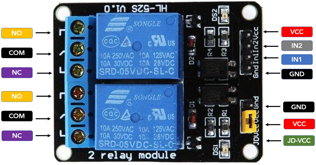
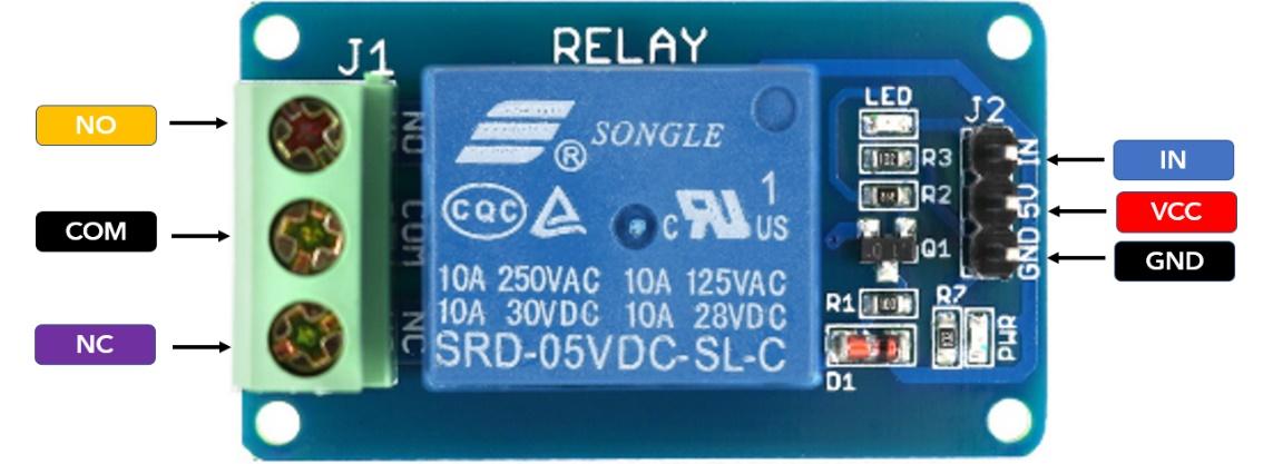
3.1: Main Voltage Connections
Main connection inside a dual channel relay module includes two different connectors with each connection having three pins NO (Normally Open), NC (Normally Closed) and Common.
Common: Control the main current (Supply voltage of external device)
Normally Closed (NC): Using this configuration relay is set to closed by default. In normal configuration current is flowing between common and NC unless a trigger signal is sent to open the circuit and stop the current flow.
Normally Open (NO): Normally open configuration is opposite to NC. By default, current is not flowing; it only starts to flow when a trigger signal is sent from ESP32.
3.2: Control Pins:
The other side of the relay module includes a set of 4 and 3 pins. The first set of low voltage sides contains four pins VCC, GND, IN1 and IN2. The IN pin varies depending upon the number of channels there is a separate IN pin for each channel.
The IN pin receives the control signal for relay from any microcontroller. When the received signal goes below 2V the relay is triggered. Following configuration can be set using the relay module:
Normally Closed Configuration:
- 1 or HIGH current START to flow
- 0 or LOW current STOP flowing
Normally Open Configuration:
- 1 or HIGH current STOP flowing
- 0 or LOW current START to flow
3.3: Power Supply Selection
The second set of pins includes the three pins VCC, GND and JD-VCC. The JD-VCC pins are normally connected to VCC which means the relay is powered using the ESP32 voltage and we don’t need an external power source separately.
If you remove the black cap connector shown in image above, then we have to power the relay module separately.
As of now we have covered all the specifications and working of the dual channel relay module. Now we will interface it with ESP32.
4: Interfacing Relay with ESP32
Now we will use any single channel from the relay module and control a LED using the ESP32 signal. Using the same technique any of the AC appliances can also be controlled but we have to power them separately. We will use the first channel of the relay module.
4.1: Schematic
Now connect the relay module as shown in image below. Here we have used GPIO pin 13 of ESP32 for the trigger signal of the relay module. A LED is connected in NC configuration.
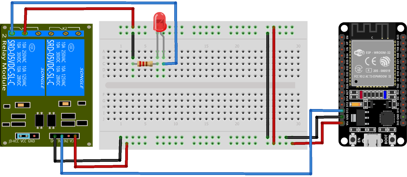
Following pin configuration will be followed:
| Relay Pin | ESP32 Pin |
| IN1 | GPIO 13 |
| VCC | Vin |
| GND | GND |
| Channel 1 NC | LED +ive Terminal |
| Common | Vin |
4.2: Code
Open Arduino IDE. Connect ESP32 with PC and upload the given code.
https://Linuxhint.com
*********/
const int Realy_2Chan = 13;
void setup() {
Serial.begin(115200);
pinMode(Realy_2Chan, OUTPUT);
}
void loop() {
digitalWrite(Realy_2Chan, HIGH); /*Using NC configuration Send HIGH for Current Flow*/
/*For NO sends LOW signal for Current Flow*/
Serial.println("LED ON-Current Flow Starts");
delay(3000); /*delay of 3 sec*/
digitalWrite(Realy_2Chan, LOW); /*Using NC configuration Send LOW To stop Current Flow*/
/*For NO sends LOW signal to stop Current Flow*/
Serial.println("LED OFF-Current Flow Stops");
delay(3000);
}
Here in above code GPIO 13 is defined as a trigger pin connected to IN1 of the relay module. Next, we defined a relay module in NC configuration which turns ON LED unless a HIGH signal is sent at IN1 from ESP32.
For NO configuration send HIGH signal at IN1 to turn ON LED.

After uploading code in the ESP32 board now observe the output.
4.3: Output
Following output can be seen on the serial monitor here we can see when LED is ON and OFF.
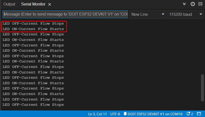
As LED is connected in NC configuration so LED will be ON.

Now a HIGH signal is sent at IN1 pin of the relay module the LED will turn OFF as the relay module is ON.
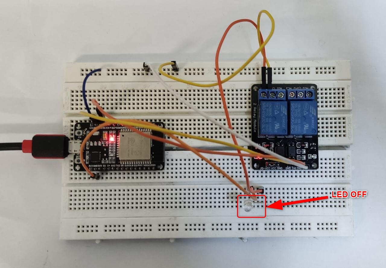
We have successfully integrated and tested the ESP32 microcontroller board with a dual channel relay module. For demonstration purposes we connected a LED at Common terminal of channel 1.
Conclusion
Using a relay with ESP32 is a great way of controlling multiple AC devices not only using a wired connection but can also be controlled remotely. This article covers all the steps needed to control a relay with ESP32. Using this article any channel relay module can be connected to ESP32.