Pulse Width Modulation or PWM is a technique used to chop the digital signal to get variable output. Most of the microcontrollers have an internal clock which is used to generate a PWM signal. In this tutorial we will be covering PWM pins and how they can be configured in ESP32 using the Arduino IDE.
PWM Pins in ESP32
The ESP32 board has 16 independent channels that can generate PWM signals. Almost all the GPIO pins that can act as output can be used to generate a PWM signal. GPIO pins 34,35,36,39 cannot be used as PWM pins as they are input only Pins.
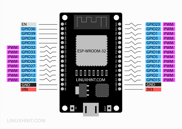
In the 36 pins variant of ESP32 board the six SPI integrated pins which cannot be used as PWM signal generators as well.
How to Use ESP32 PWM Pins
PWM is a technique to control the device using a variable digital pulse signal. PWM helps in controlling motor speed. Main component in generating PWM signals is the internal timer module. Timer is controlled by the internal microcontroller clock source.
As time starts its value is compared with two comparators and once it reaches the defined duty cycle value a signal at PWM pin is triggered which changes pin states to LOW. Next the timer signal goes on counting till it achieves the period register value. Now again the comparator will generate a new trigger and PWM pins state shift from LOW to HIGH.
To generate a PWM signal at GPIO pins following four properties need to be defined:
- PWM Frequency: Frequency for PWM is opposite to the time Any value can be set depending upon application.
- PWM Resolution: Resolution defines the number of discrete levels of duty cycle that can be controlled.
- Duty Cycle: Amount of time during which a PWM signal is in active state.
- GPIO Pin: Pin number of ESP32 where PWM signal is to be read. (GPIO 34,35,36,39 cannot be used)
Configure PWM Channels of ESP32
Configuring the PWM channel in ESP32 is similar to the analogWrite() function in Arduino programming. But here we will be using a dedicated set of ledcSetup() functions for configuring PWM in ESP32. Pretty much everything needed for a PWM signal like channel, resolution and frequency can be easily configurable by the user.
Following is the ledcSetup() function used to configure ESP32 PWM signal:
This function contains three arguments.
Channel: As ESP32 has 16 PWM channels so the channel argument inside the ledcSetup() function can take any value between 0 and 15.
Frequency: Next in the ledcSetup() function we have frequency arguments which can be set according to requirements like 1 KHz, 5 KHz, 8 KHz, and 10 KHz. For example, Maximum PWM frequency with 10 bits resolution in the PWM module can be set is 78.125KHz.
Resolution: PWM signal resolution can be configured between 1 bit to 16-bit resolution.
In ESP32 both PWM frequency and resolution are independent of clock source and inversely proportional.
Final step is to define a pin for PWM. Don’t assign already used pins for communication such as GPIO pins like UART, SPI, etc.
The LEDC (LED PWM Controller) is primarily designed for ESP32 PWM LED control signals. However, PWM signals generated here can also be used for other applications.
Here are some points which one needs to keep in mind while configuring ESP32 PWM signal:
- Total of 16 independent PWM Channels are in ESP32 which are divided into two groups each group having 8 channels.
- 8 PWM channels are high speed while the other 8 channels are LOW.
- PWM resolution can be set between 1-bit and 16-bits.
- PWM frequency is dependent upon the resolution of PWM.
- Duty cycle can be automatically increased or decreased without processor intervention.
Controlling LED Brightness Using PWM Signal in ESP32
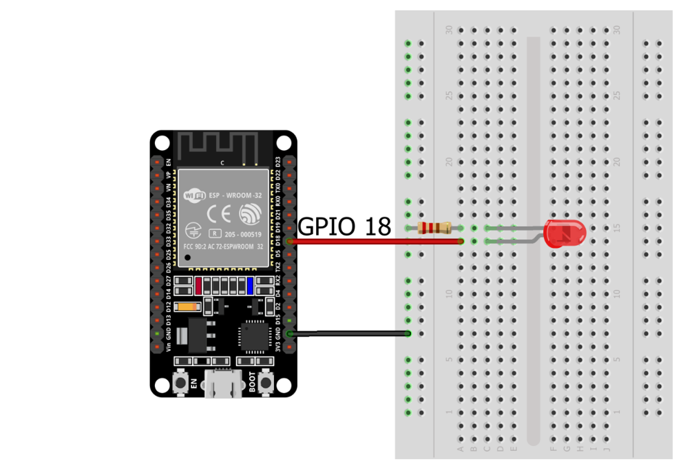
Now we will control LED brightness using a PWM signal. Connect LED with ESP32 GPIO pin 18.
The table shows the pin connection for LEDs with ESP32.
| ESP32 GPIO Pin | LED |
| GPIO 18 | +ive |
| GND | -ive |
Code for LED Brightness Control
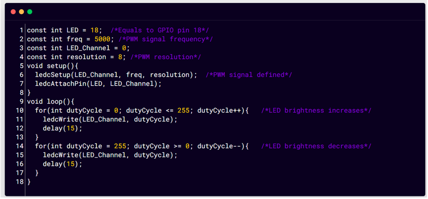
The code given below will make the LED fade in and out:
const int freq = 5000; /*PWM signal frequency*/
const int LED_Channel = 0;
const int resolution = 8; /*PWM resolution*/
void setup(){
ledcSetup(LED_Channel, freq, resolution); /*PWM signal defined*/
ledcAttachPin(LED, LED_Channel);
}
void loop(){
for(int dutyCycle = 0; dutyCycle = 0; dutyCycle--){ /*LED brightness decreases*/
ledcWrite(LED_Channel, dutyCycle);
delay(15);
}
}
Code started by defining the pin number for LED which is GPIO 18. Next we set the PWM signal properties which are frequency, PWM signal resolution and LED channel.
Next using the ledcSetup() function we configure the PWM signal. This function accepts the three arguments frequency, resolution and LED channel we have defined earlier.
In the loop part we vary the duty cycle between 0 and 255 to increase the brightness of the LED. After that again using the for loop decreases the LED brightness from 255 to 0.
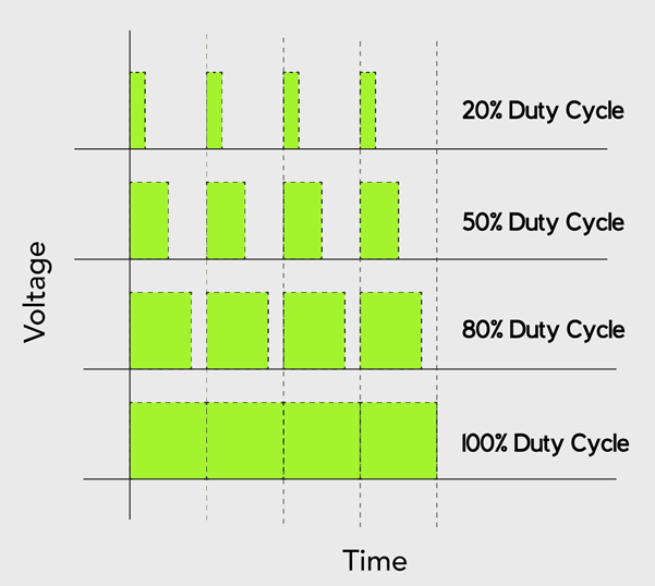
Pulse width modulation turns a digital signal into an analog signal by changing the timing of how long it stays on and off. The term Duty cycle is used to describe the percentage or ratio of how long it stays on compared to when it turns off.
Here we have taken an 8-bit channel so according to calculations:
2^8 =256 containing values from 0 to 255. In the example given above the duty cycle is equal to 100%. For 20% duty cycle or any other value we can calculate it using the below calculations:
Channel resolution = 8 bit
For 100% duty cycle = 0 to 255 (2^8=256 values)
For 20% duty cycle = 20% of 256 is 51
So a 20% duty cycle of 8-bit resolution will equal values of range 0 to 51.
Where 0 = 0% and 51 = 100% of 8-bit resolution duty cycle.
Output
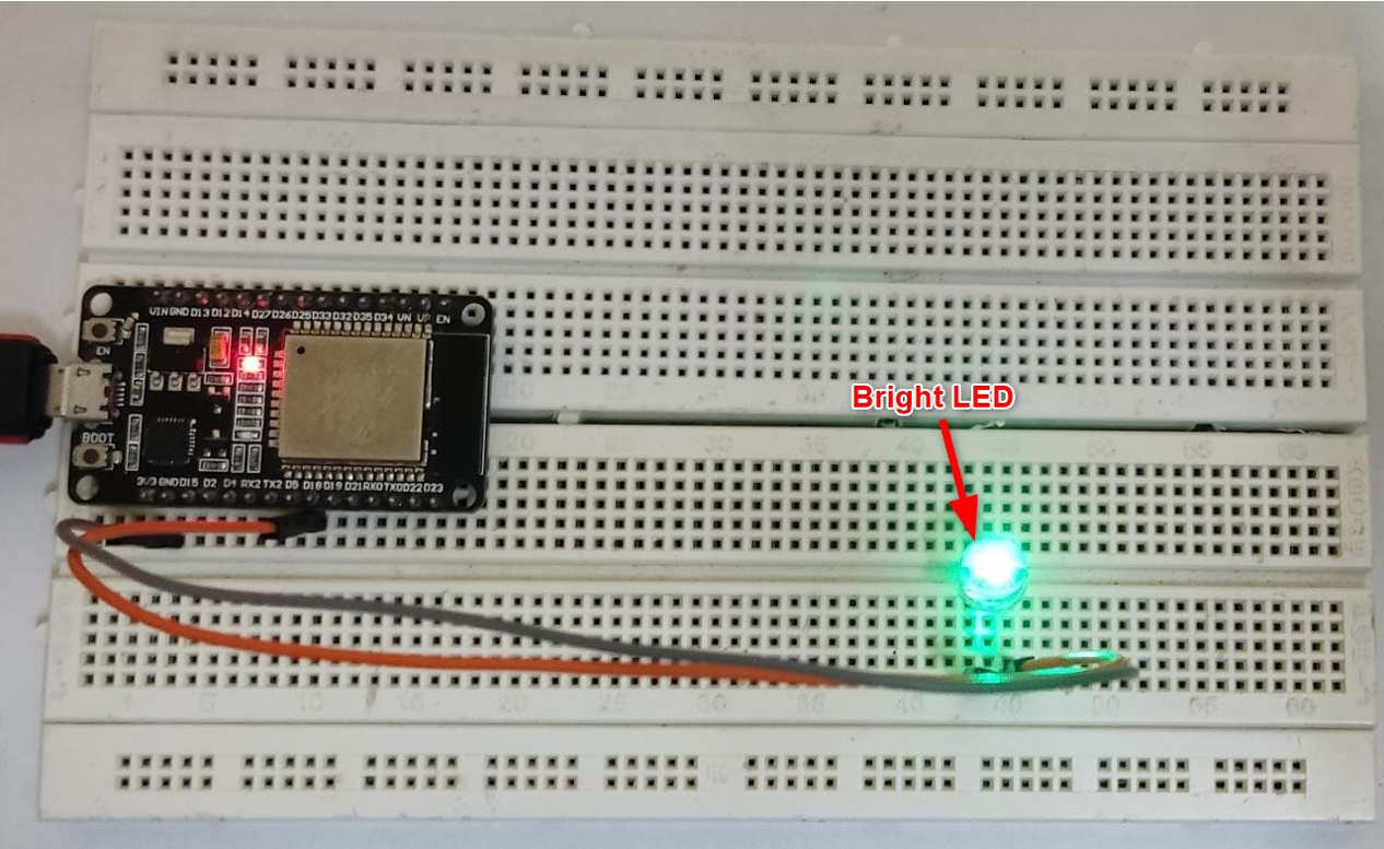
On hardware we can see the brightness of the LED at its full, this means the duty cycle signal is at 255.
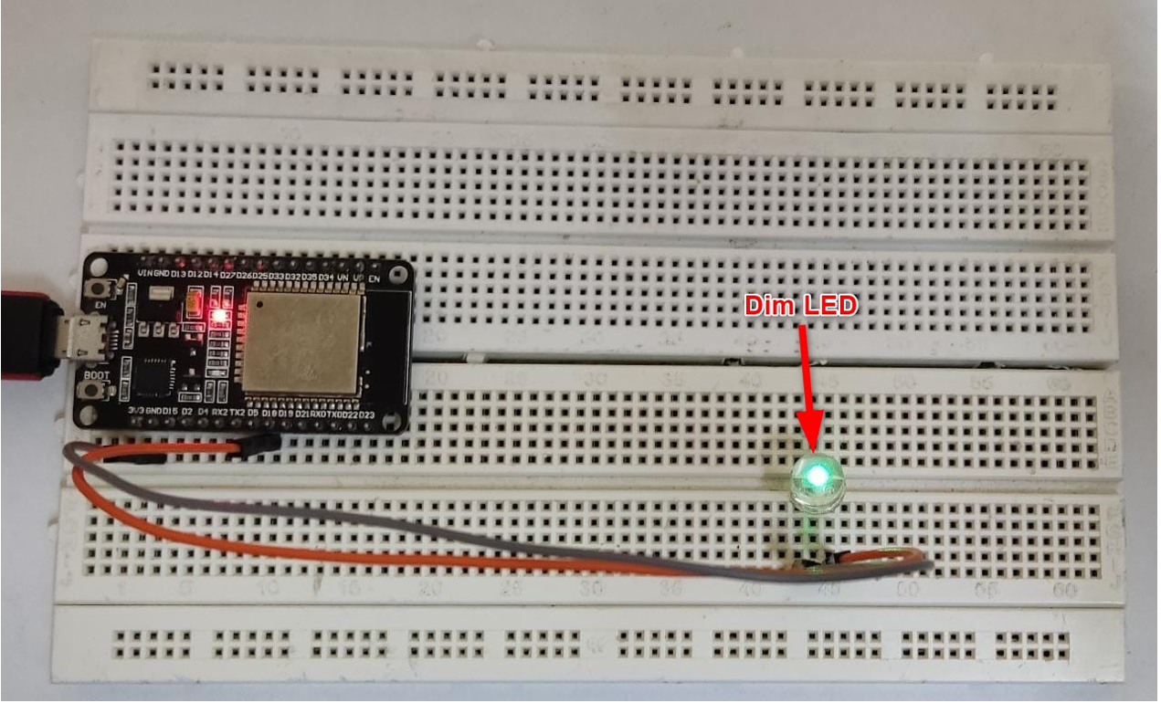
Now we can see the LED is completely dim, which means the duty cycle value is at 0.
We have successfully controlled LED brightness using the PWM signal.
Conclusion
Here in this article, we have discussed ESP32 PWM pins and how they can be used for controlling multiple peripherals like LED or motor. We also discussed the code for controlling single and multiple LEDs using the same PWM channel. Using this guide any type of hardware can be controlled with the help of PWM signal.

