Following is the list of contents:
- 1: Introduction to Keypad
- 2: Working of keypad
- 3: 4X4 keypad Pinout
- 4: Interfacing ESP32 with 4X4 Keypad
- Conclusion
1: Introduction to Keypad
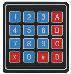
A keypad is a type of input device that can be used to interface with an ESP32 microcontroller. It typically consists of a matrix of buttons or keys that can be used to input numeric or alpha-numeric data.
The keypad is connected to the ESP32 via a set of digital pins and can be used in a variety of applications such as password protection systems, data entry systems, or as a simple input method for interactive projects.
The Arduino keypad library allows for easy programming and implementation of the keypad, providing functions for reading the state of the keys and detecting button presses.
2: Working of Keypad
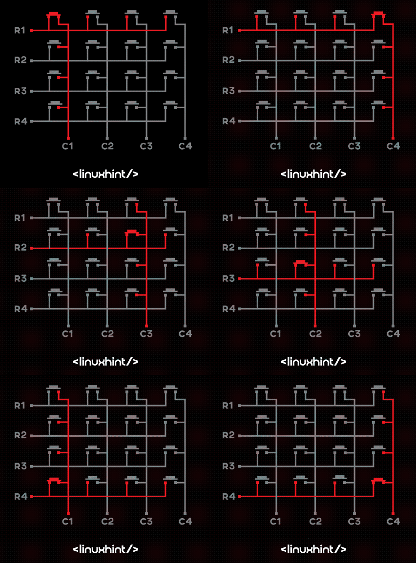
The working of a keypad involves a combination of hardware and software components. On the hardware side, the keypad typically consists of a matrix of buttons or keys that are connected to the ESP32 via a set of digital pins.
The keypad is designed to send a unique signal to the ESP32 for each button press, which the microcontroller can then interpret and process.
On the software side, the Arduino keypad library provides a set of functions that can be used to read the state of the keys and detect button presses. These functions allow the user to define the behavior of the keypad.
The Arduino code for ESP32 reads the digital input pins connected to the keypad and identifies the button press by checking the voltage level on those pins. It then sends the corresponding ASCII code, or the number pressed to the microcontroller, where the code written by the user processes it further.
3: 4X4 Keypad Pinout
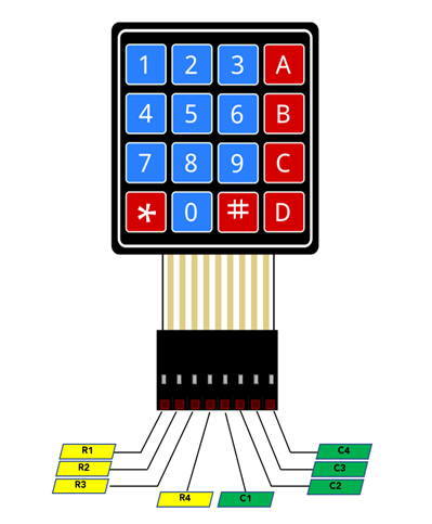
The pinout for a 4×4 keypad typically consists of 8 pins, 4 for the rows and 4 for the columns. Here is an example of the pinout for a 4×4 keypad:
It is worth noting that the pinout may vary depending on the specific keypad you are using and the wiring scheme you choose.
4: Interfacing ESP32 with 4X4 Keypad
To read input from the keypad first we have to install the keypad Library in Arduino IDE. After that, using the digital pins and library code, we can read data from the keypad.
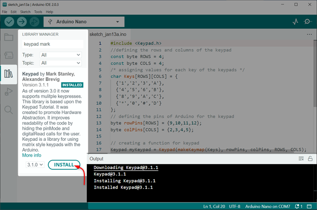
4.1: Installing the Required Libraries
Open library manager in IDE and search keypad library by Mark Stanley. Install the library in IDE:
After installing the keypad library now, we can interface it with the ESP32 board.
4.2: Schematic
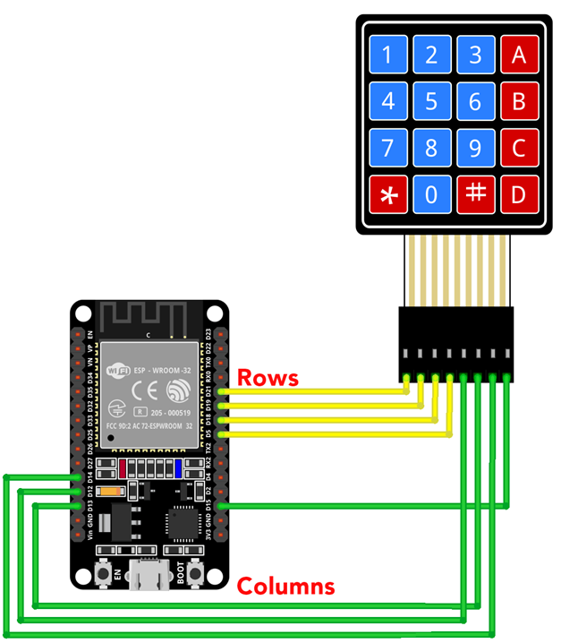
Connect ESP32 with the keypad as displayed in the image:
Following is the pin configuration table of ESP32 with keypad:
| keypad Pin | ESP32 |
|---|---|
| Row 1 | D21 |
| Row 2 | D19 |
| Row 3 | D18 |
| Row 4 | D5 |
| Column 1 | D12 |
| Column 2 | D13 |
| Column 3 | D14 |
| Column 4 | D15 |
4.3: Hardware
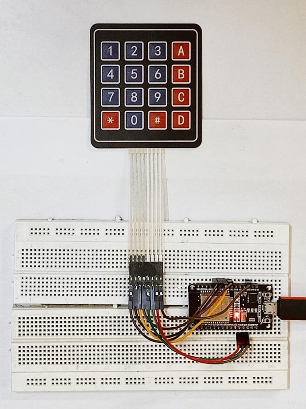
In hardware ESP32 can be seen on breadboard connected with keypad using jumper wires:
4.4: Code
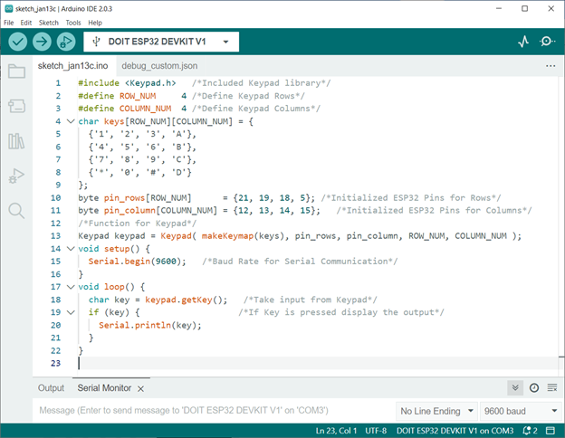
Open IDE and upload keypad code to ESP32 board:
#define ROW_NUM 4 /*Define keypad Rows*/
#define COLUMN_NUM 4 /*Define keypad Columns*/
char keys[ROW_NUM][COLUMN_NUM] = {
{'1', '2', '3', 'A'},
{'4', '5', '6', 'B'},
{'7', '8', '9', 'C'},
{'*', '0', '#', 'D'}
};
byte pin_rows[ROW_NUM] = {21, 19, 18, 5}; /*Initialized ESP32 Pins for Rows*/
byte pin_column[COLUMN_NUM] = {12, 13, 14, 15}; /*Initialized ESP32 Pins for Columns*/
/*Function for keypad*/
keypad keypad = keypad( makeKeymap(keys), pin_rows, pin_column, ROW_NUM, COLUMN_NUM );
void setup() {
Serial.begin(9600); /*Baud Rate for Serial Communication*/
}
void loop() {
char key = keypad.getKey(); /*Take input from keypad*/
if (key) { /*If Key is pressed display the output*/
Serial.println(key);
}
}
Code started by including the keypad library. At the start of the code the dimension of the keypad is defined. As we are using the 4X4 keypad so total Rows and Columns are defined.
Next using the keypad library function code will read the input if any button is pressed. Serial baud rate is initialized to display the pressed button on the IDE serial monitor:
4.5: Output
Once the code is uploaded press a key on the keypad you will see the same output on serial monitor of IDE:
We have completed the interfacing of ESP32 with the keypad.
Conclusion
ESP32 is an IoT based microcontroller board that can read data using its digital pins. A 4×4 keypad can be interfaced with ESP32 using 8 digital pins. Total of four pins are for the rows and the remaining four are for the column input. We can read different numbers through ESP32 digital pins using the keypad and display it on the serial monitor of the IDE.

