ESP32-WROVER-KIT is a development board that comes equipped with the ESP32-Wrover module, designed to offer high-performance computing capabilities for embedded systems. This kit features a 240MHz dual-core Tensilica LX6 microcontroller with 8MB of PSRAM and 4MB of flash memory. In this article, we will take a closer look at the ESP32-Wrover Kit and its features, as well as explore its applications and benefits.
Introduction to ESP32-WROVER-KIT
The ESP-WROVER-KIT is a development board manufactured by Espressif that is built around the ESP32-WROVER-E module and comes equipped with an LCD screen and a microSD card slot.
One of the board’s notable features is the FTDI FT2232HL chip, a multi-interface USB bridge. This chip allows for JTAG-based debugging of the ESP32 via the USB interface without the need for a separate JTAG debugger.
The ESP-WROVER-KIT offers easy access to most of the ESP32’s I/O pins through the board’s pin headers.
Features of the ESP32-WROVER-KIT
The ESP32-WROVER-KIT comes with a wide range of features that make it an ideal choice for embedded systems development. Some of the key features include:
- Dual-core Tensilica LX6 microcontroller with clock speeds of up to 240MHz
- 8MB of PSRAM and 4MB of flash memory
- Built-in WiFi and Bluetooth connectivity
- MicroSD card slot for external storage
- JTAG debugging interface for advanced debugging capabilities
- 3.2-inch touch display with a resolution of 320×240 pixels
Function Description of ESP32-WROVER-KIT
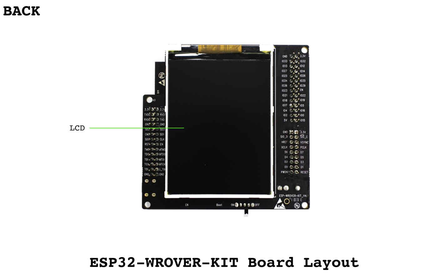
The following two figures and the table below describe the key components, interfaces, and controls of the ESP-WROVER-KIT board.
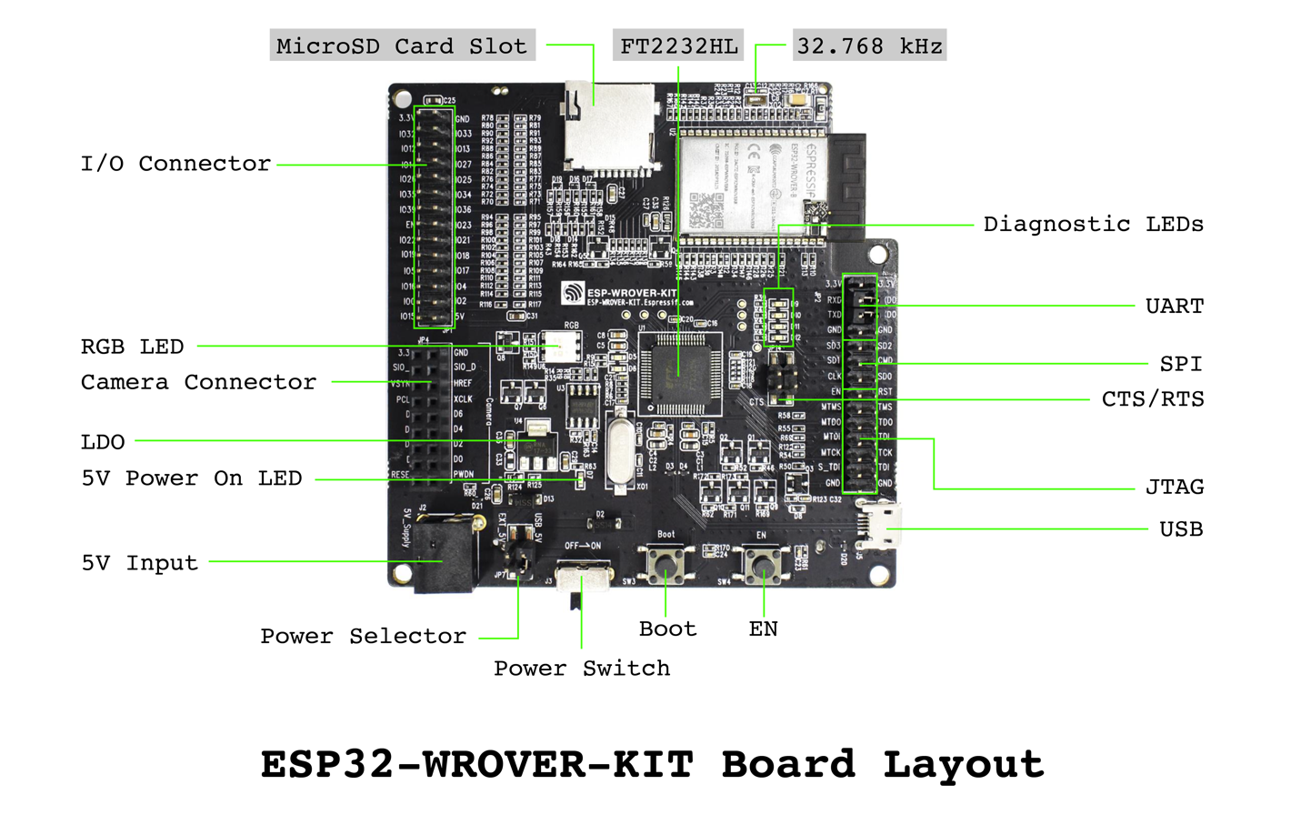
The below given table discussed the different properties of key components of ESP32-WROVER-KIT:
| Key Component | Description |
|---|---|
| FT2232HL | FT2232HL is a USB-to-serial bridge chip that enables communication with ESP32 and can be controlled via USB. It has two channels, A and B, where channel A provides USB-to-JTAG interface, and channel B provides USB-to-serial interface. |
| 32.768 kHz | A 32.768 kHz crystal oscillator is used as a low-power clock during Deep-sleep mode. |
| 0R | A zero-ohm resistor acts as a placeholder for a current shunt that can be removed or replaced with a current shunt for measuring ESP32’s current consumption in various modes. |
| ESP32-WROVER-E module | The ESP32 module has 64-Mbit PSRAM, allowing for extended storage and data processing capabilities. |
| Diagnostic LEDs | Four red LEDs are connected to FT2232HL’s GPIO pins. |
| UART | The serial TX/RX signals of ESP32 and FT2232HL are accessible through JP2 with default jumper connections. To use the ESP32’s serial interface with an external device, the jumpers must be removed. |
| SPI | ESP32 uses its SPI interface to access internal flash and PSRAM memory by default. To connect ESP32 to an external SPI device, use these pins and an additional chip select (CS) signal. The voltage for this interface is 3.3 V. |
| CTS/RTS | The serial port flow control signals are not connected to the circuitry by default. To activate them, use jumpers to connect the corresponding pins of JP14. |
| JTAG | The JTAG signals of FT2232HL and ESP32 are accessible through JP2 with default disconnections. To enable JTAG, connect the corresponding pins with jumpers. |
| USB Port | The USB interface serves as both the power supply and communication link between a computer and the board. |
| EN Button | Reset button. |
| BOOT Button | Pressing and holding Boot, then pressing EN activates Firmware Download mode. |
| Power Switch | The Power On/Off Switch turns the board on when toggled towards the Boot button and turns it off when toggled away from Boot. |
| Power Selector | The board can be powered either through USB or the 5V Input interface. Choose the power source using a jumper on JP7. |
| 5V Input | The board has a 5V power supply interface that uses a standard coaxial power connector measuring 5.5 x 2.1 mm with a center-positive polarity. This interface is useful when the board is operating independently of a computer. |
| 5V Power On LED | The red LED illuminates when the board is powered on, whether through USB or 5V Input. |
| LDO | The board includes an NCP1117 LDO that converts 5V to 3.3V, with a maximum output current of 1A. The built-in LDO has a fixed output voltage, but it can be replaced with an adjustable LDO by the user. |
| Camera Connector | Camera interface, a standard OV7670 camera module. |
| RGB LED | The board has red, green, and blue (RGB) LEDs that can be controlled using pulse width modulation (PWM). |
| I/O Connector | All the pins on the ESP32 module are accessible via pin headers and can be programmed to perform various functions such as PWM, ADC, DAC, I2C, I2S, SPI, and more. |
| microSD Card Slot | The board is suitable for developing applications that require access to a microSD card for data storage and retrieval. |
| LCD | The board supports the mounting and interfacing of a 3.2″ SPI (Serial Peripheral Interface) LCD using the standard 4-wire interface. |
Conclusion
The ESP32-WROVER-KIT is a powerful development board that offers high-performance computing capabilities for embedded systems. Its built-in Wi-Fi and Bluetooth connectivity, 8MB of PSRAM and 4MB of flash memory, and dual-core Tensilica LX6 microcontroller make it an ideal choice for a wide range of applications, including robotics and IoT devices.