
Setting up an ESP32 NTP Analog clock is relatively straightforward, as the ESP32 has built-in support for NTP and there are many libraries available to assist with the OLED display. Once configured, the ESP32 NTP clock can be used to keep track of the time with high accuracy, even when disconnected from the internet.
Now we will design a NTP based Analog clock using ESP32.
Equipment required
To design a NTP internet-based Analog clock using ESP32 following components are required:
- ESP32 Board
- 128X64 I2C OLED Display
- Connecting Wires
- Breadboard
Introduction to NTP (Network Time Protocol)
The NTP is a networking protocol that synchronizes the clocks of multiple systems with the NTP server. It is used to ensure that the clocks on different devices are in sync with each other, even if they are in different parts of the world.
NTP works by using a hierarchy of time servers, with each server synchronizing its clock with a more accurate time source. This allows devices to synchronize their clocks with a high level of accuracy, typically within a few milliseconds.
NTP is an important protocol for many applications, including computer networks, financial transactions, and scientific research. It is also used to synchronize the time displayed on digital clocks and other devices.
How Does NTP Work?
The Network Time Protocol (NTP) works by sending and receiving timestamps between servers and clients, using a combination of the current time and the time taken for the message to be sent and received.
The NTP server maintains a high-precision reference clock and uses this clock to adjust the clocks on other devices. The NTP client sends a request to the server, and the server responds with the current time and other data, such as the round-trip time of the request and the server’s current time. The client then uses this information to adjust its own clock and maintain accurate time.
The NTP client adjusts its local clock with the online NTP server using the link delay and local offset defined inside the Arduino code.
Internet Analog Clock with ESP32 & OLED Display Using NTP Client
Designing a real time NTP server-based Analog clock using ESP32 has many benefits. As it is not dependent upon the internal RTC module so we can get exact time using the NTP server. To design this clock first we have to install some necessary libraries in the Arduino IDE.
Installing the Required Libraries
To make ESP32 internet clock using NTP server and display the time on OLED screen, we need to install following libraries:
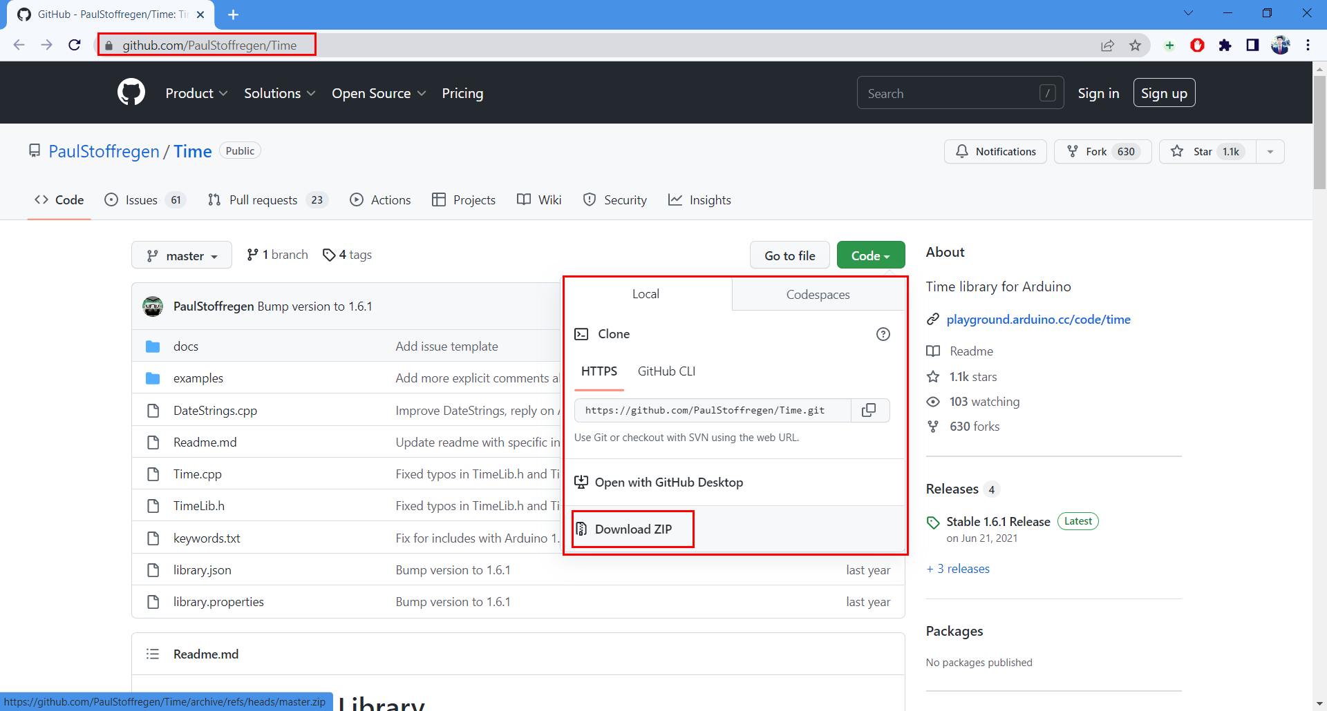
- Download Time Library
- Download GFX Library
- Download Adafruit OLED 1306 Library
To download Time Library open the link and click Download Zip.
After downloading Time library open IDE and go to: Sketch > Include Library > Add .ZIP Library
Now to display time on the OLED screen, open the library manager and install the SSD1306 library by Adafruit.

Now install the GFX library written by Adafruit.

Wiring the OLED to the ESP32
It is possible to connect an OLED display with an ESP32 via its I2C pins. SDA pin is at D21 and SCL/SCK is at D22.
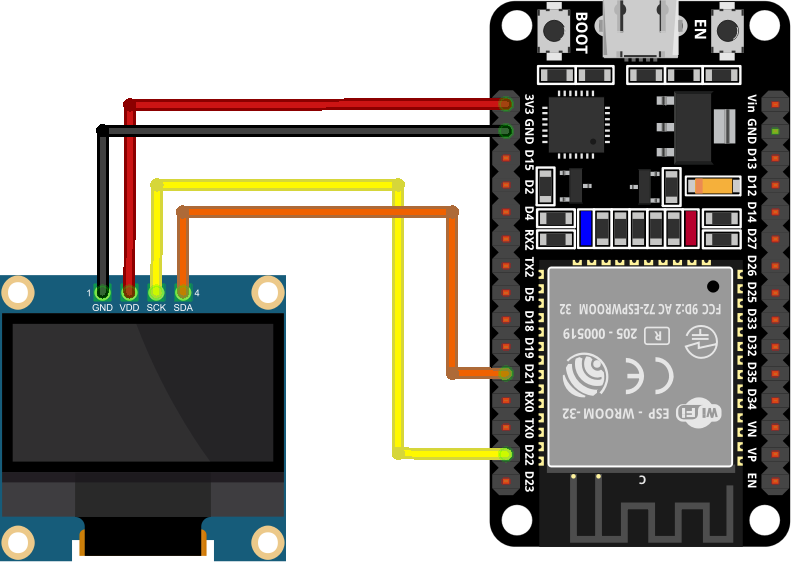
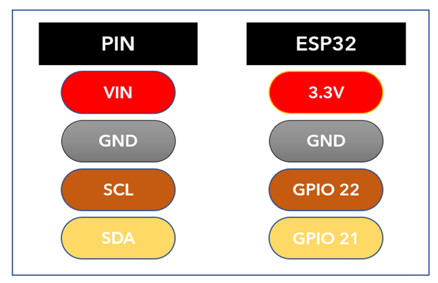
Following are the connections:
| I2C OLED | ESP32 |
| VCC | VIN/3V3 |
| GND | GND |
| SDA | D21 |
| SCL | D22 |
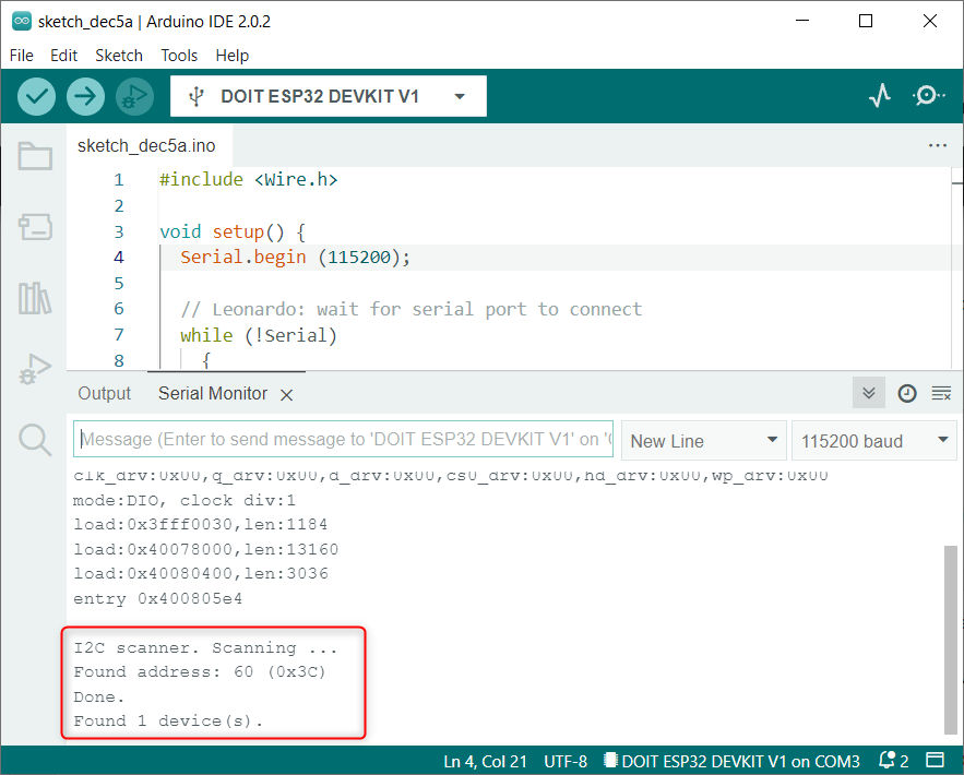
Getting the OLED Display I2C Address
After connecting I2C OLED with ESP32 it’s important to check the I2C address. In case if one is using more than one device on the same I2C bus then ESP32 will be unable to communicate with both.
Always use devices with different I2C addresses. To get the I2C address we will use the Wire library. For more detailed-on Arduino code read the article Get I2C Address in ESP32 Using Arduino IDE.
Here the OLED we are using has an I2C address 0X3C.
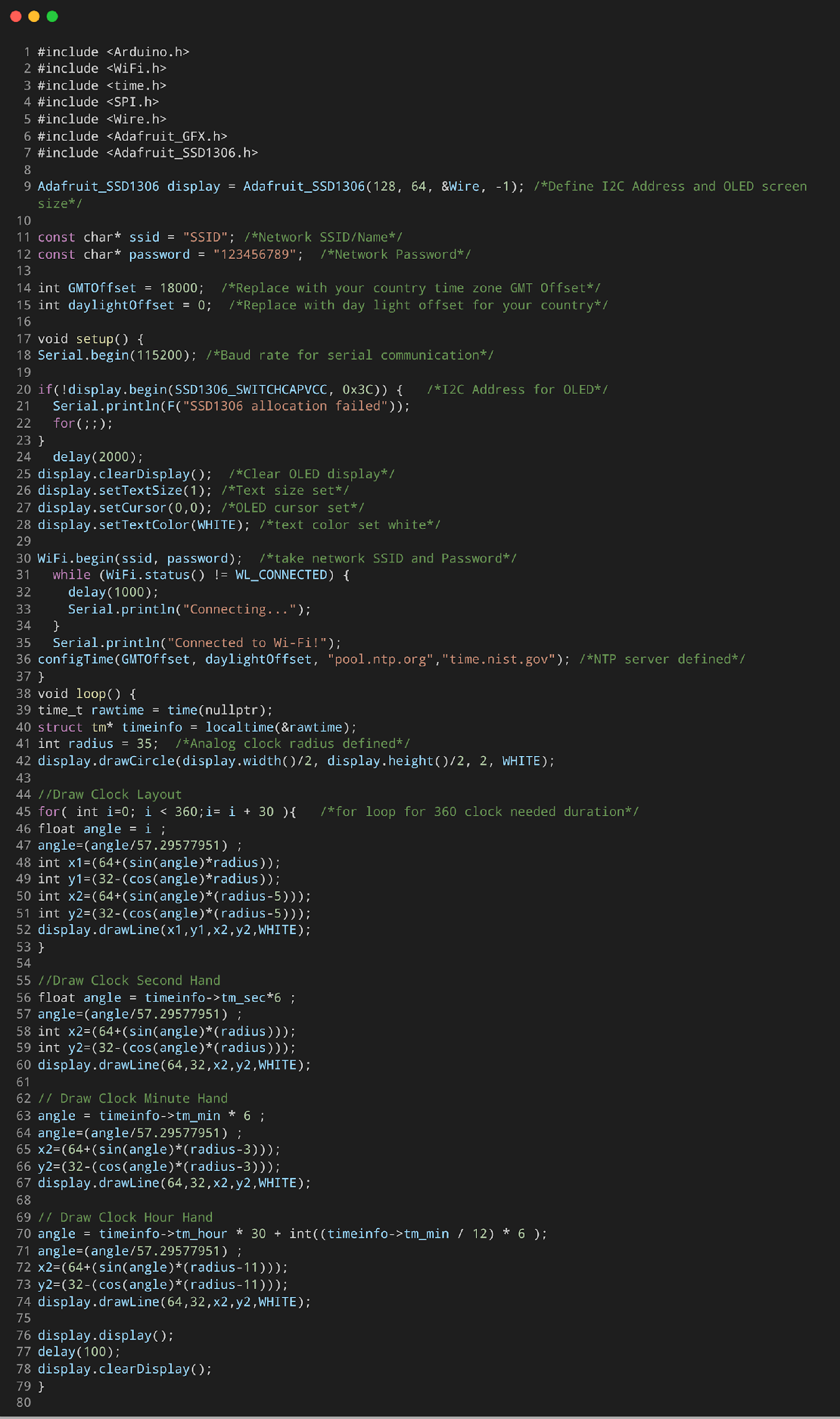
Code for ESP32 Internet Analog Clock
Open IDE and upload code to connect to a NTP server. Once ESP32 is connected to NTP server using the WiFi connection defined inside the code, Arduino serial monitor, and I2C OLED will display real time.
#include <WiFi.h>
#include <time.h>
#include <SPI.h>
#include <Wire.h>
#include <Adafruit_GFX.h>
#include <Adafruit_SSD1306.h>
Adafruit_SSD1306 display = Adafruit_SSD1306(128, 64, &Wire, -1); /*Define I2C Address and OLED screen size*/
const char* ssid = "SSID"; /*Network SSID/Name*/
const char* password = "123456789"; /*Network Password*/
int GMTOffset = 18000; /*Replace with your country time zone GMT Offset*/
int daylightOffset = 0; /*Replace with daylight offset for your country*/
void setup() {
Serial.begin(115200); /*Baud rate for serial communication*/
if(!display.begin(SSD1306_SWITCHCAPVCC, 0x3C)) { /*I2C Address for OLED*/
Serial.println(F("SSD1306 allocation failed"));
for(;;);
}
delay(2000);
display.clearDisplay(); /*Clear OLED display*/
display.setTextSize(1); /*Text size set*/
display.setCursor(0,0); /*OLED cursor set*/
display.setTextColor(WHITE); /*text color set white*/
WiFi.begin(ssid, password); /*take network SSID and Password*/
while (WiFi.status() != WL_CONNECTED) {
delay(1000);
Serial.println("Connecting...");
}
Serial.println("Connected to Wi-Fi!");
configTime(GMTOffset, daylightOffset, "pool.ntp.org","time.nist.gov"); /*NTP server defined*/
}
void loop() {
time_t rawtime = time(nullptr);
struct tm* timeinfo = localtime(&rawtime);
int radius = 35; /*Analog clock radius defined*/
display.drawCircle(display.width()/2, display.height()/2, 2, WHITE);
//Draw Clock Layout
for( int i=0; i< 360;i= i + 30 ){ /*for loop for 360 clock needed duration*/
float angle = i ;
angle=(angle/57.29577951) ;
int x1=(64+(sin(angle)*radius));
int y1=(32-(cos(angle)*radius));
int x2=(64+(sin(angle)*(radius-5)));
int y2=(32-(cos(angle)*(radius-5)));
display.drawLine(x1,y1,x2,y2,WHITE);
}
//Draw Clock Second Hand
float angle = timeinfo->tm_sec*6 ;
angle=(angle/57.29577951) ;
int x2=(64+(sin(angle)*(radius)));
int y2=(32-(cos(angle)*(radius)));
display.drawLine(64,32,x2,y2,WHITE);
// Draw Clock Minute Hand
angle = timeinfo->tm_min * 6 ;
angle=(angle/57.29577951) ;
x2=(64+(sin(angle)*(radius-3)));
y2=(32-(cos(angle)*(radius-3)));
display.drawLine(64,32,x2,y2,WHITE);
// Draw Clock Hour Hand
angle = timeinfo->tm_hour * 30 + int((timeinfo->tm_min / 12) * 6 );
angle=(angle/57.29577951) ;
x2=(64+(sin(angle)*(radius-11)));
y2=(32-(cos(angle)*(radius-11)));
display.drawLine(64,32,x2,y2,WHITE);
display.display();
delay(100);
display.clearDisplay();
}
Code started by calling the installed libraries OLED Adafruit, GFX Adafruit, ESP32 WiFi, and Time library.
- WiFi.h: This library will connect ESP32 to the local network.
- Time.h: This library will synchronize ESP32 time with NTP server according to our time zone.
- Wire.h and SPI.h: This library will allow ESP32 to communicate over I2C protocol.
- OLED Adafruit: This library will display animations and Analog clock needles on screen.
Using the above code, we can get NTP Time from Server. To get the correct time on OLED you have to make changes according to your time zone.
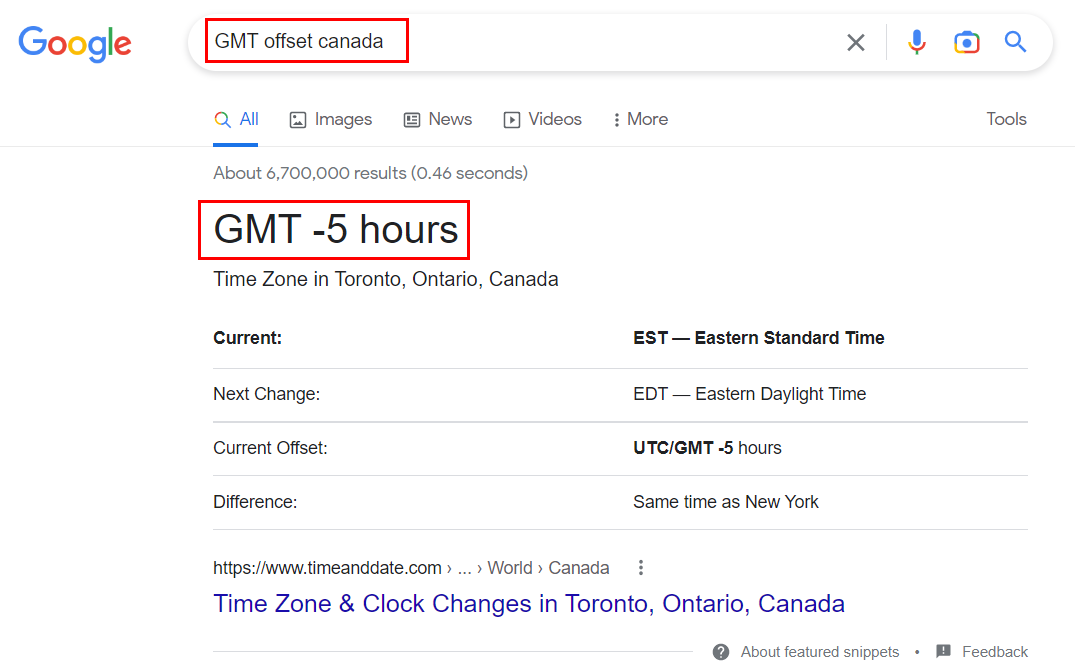
The present time zone for my country is 5 hours ahead of UTC (Universal Coordinated) Time. So, I must convert 5 hours to Seconds.
Two variables are defined GMTOffset and daylightOffset. Here we have taken GMT offset as +5 and daylightOffset is 0.
Change this time zone according to your location. You can use google to check the GMT offset for your country.
Additionally change the network SSID and Password defined inside the code.
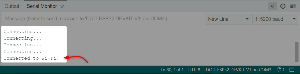
Output
On the serial monitor we can see ESP32 is connecting to the local wireless network.
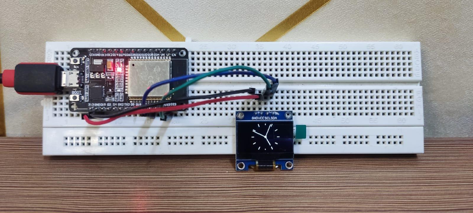
On OLED display an Analog clock with updated time can be seen.
Conclusion
ESP32 is a compact microcontroller based IoT board. This article covers all steps needed to design a real time NTP server-based Analog clock. The output is displayed on an OLED screen using the Arduino code. By setting the correct NTP server any one can design Analog clocks based on their time zone using the ESP32 and Arduino code.