This article will sum up all the steps needed to interface the ESP32 with the Blynk IoT application.
Following is the content list:
1: Introduction to Blynk Application
2: Interfacing Blynk App with ESP32 over WiFi
3: Designing LED Control GUI on Blynk Platform
4: Designing LED Control GUI on Blynk Mobile Application
1: Introduction to Blynk Application
Blynk is a user-friendly mobile application that enables individuals to control IoT devices, such as the ESP32, remotely. With its intuitive drag-and-drop interface, Blynk makes it easy for users to set up and manage their connected devices, regardless of their technical expertise.
The Blynk app communicates with the ESP32 through a cloud server, allowing us to control devices over the internet. This opens a wide range of possibilities for automation and control, making Blynk a powerful tool for makers, hobbyists, and professionals alike.
2: Interfacing Blynk App with ESP32 over WiFi
For interfacing Blynk application with ESP32 we will be using the onboard WiFi driver module. To connect ESP32 with Blynk platform an Arduino Library is also needed to be installed in IDE.
By establishing a connection between the ESP32 and the Blynk app, users can easily monitor and control their devices from anywhere with internet access. This gives multiple possibilities for automating processes and gathering data from connected devices.
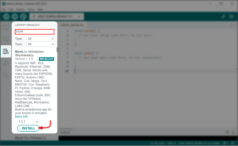
2.1: Installing the Arduino Blynk Library
Open IDE and install the Blynk library by Volodymyr:
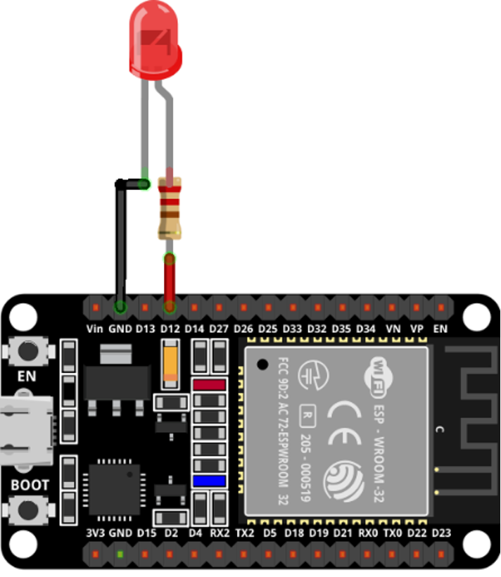
2.2: Schematic
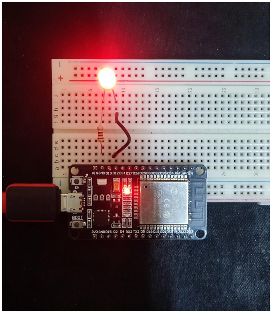
Once the library is installed connect ESP32 with a LED at pin D12:
2.3: Code
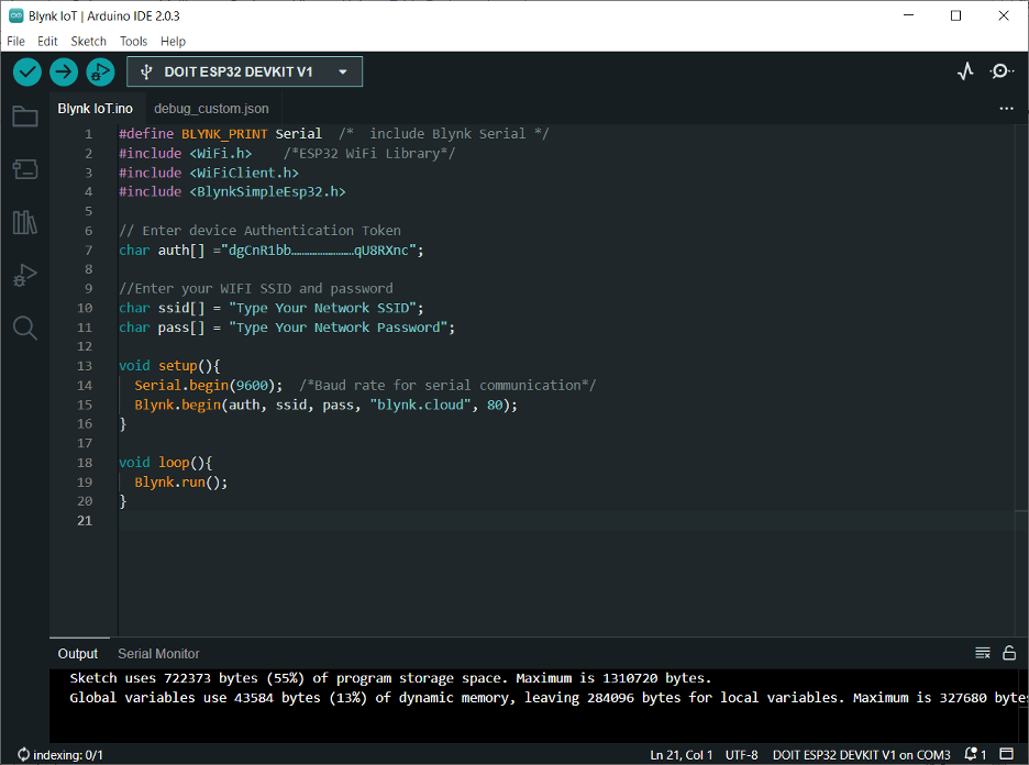
Upload the given code to the ESP32 board using the IDE:
#include <WiFi.h> /*ESP32 WiFi Library*/
#include <WiFiClient.h>
#include <BlynkSimpleEsp32.h>
// Enter device Authentication Token
char auth[] ="dgCnR1bb……………………qU8RXnc";
//Enter your WIFI SSID and password
char ssid[] = "Type Your Network SSID";
char pass[] = "Type Your Network Password";
void setup(){
Serial.begin(9600); /*Baud rate for serial communication*/
Blynk.begin(auth, ssid, pass, "blynk.cloud", 80);
}
void loop(){
Blynk.run();
}
This code will establish the communication between ESP32 and Blynk IoT platform. First, we must define the required libraries. After that the authentication token will be initialized.
Note: This Authentication token can be obtained from Blynk IoT dashboard which we will explain later in this article.
Define the network SSID and Password to connect ESP32 with an online network. After that ESP32 will establish the connection with the Blynk IoT platform:
Now as ESP32 is connected with the Blynk application we can design a GUI for LED controlling.
3: Designing LED Control GUI on Blynk Platform
To design a GUI for LED control. We need to sign up and do some settings in the Blynk IoT dashboard. Follow the steps for further guidance:
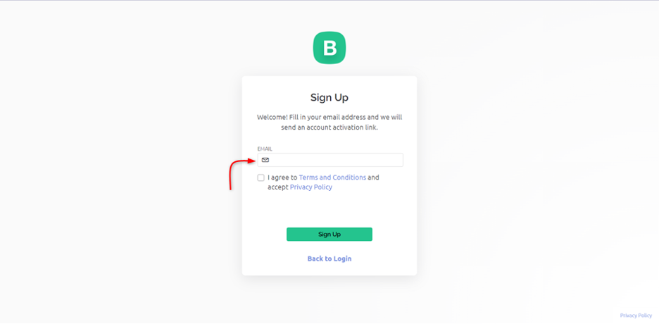
Step 1: Open Blynk.cloud. Signup or login to create a new account:
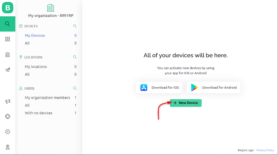
Step 2: After signing in to Blynk. Create a new device such as ESP32:
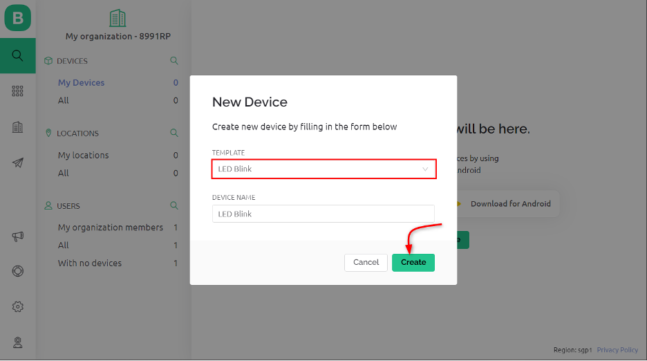
Step 3: Here we are creating a GUI for LED control at pin D12 so we named our device as LED Blink:
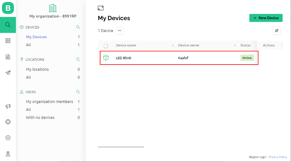
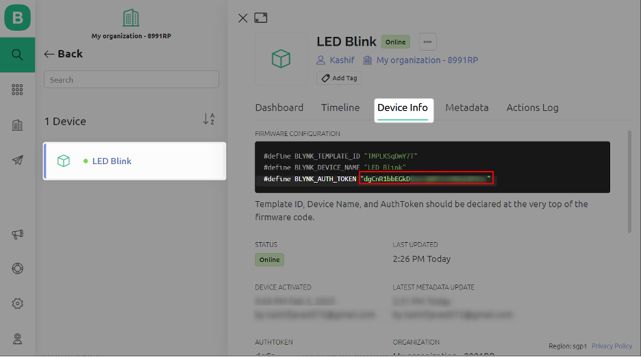
Step 4: A new device LED Blink is created:
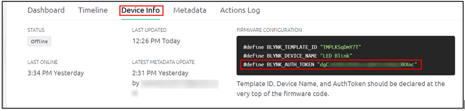
Step 5: Under the device info section we can see the authentication token which we used in Arduino IDE code:
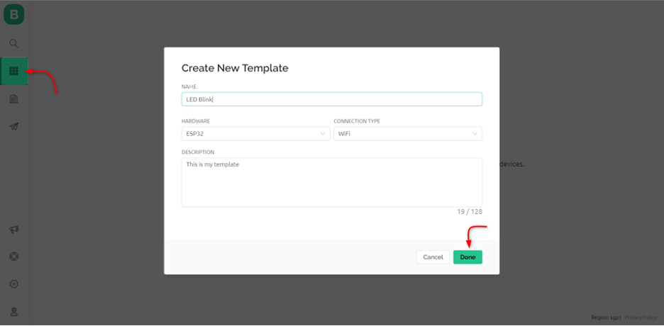
Step 6: Now open a new template. Here we can select the hardware name and connection type which in our case is WiFi. Click Done to save the setting:
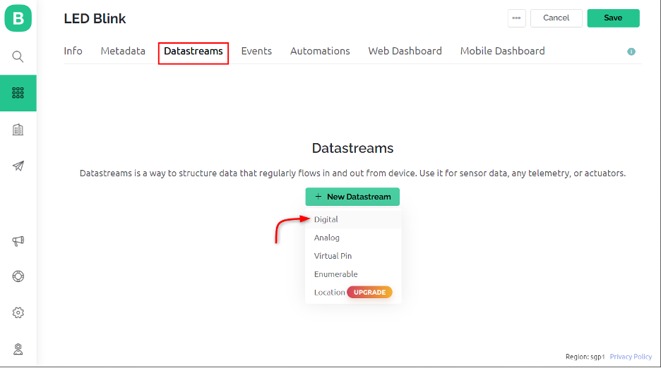
Step 7: Once the new template is created, we can add a data stream in our project. Using these data streams, we can control any ESP32 pin. As we need to control a LED so we will be using the digital pin for data streams:
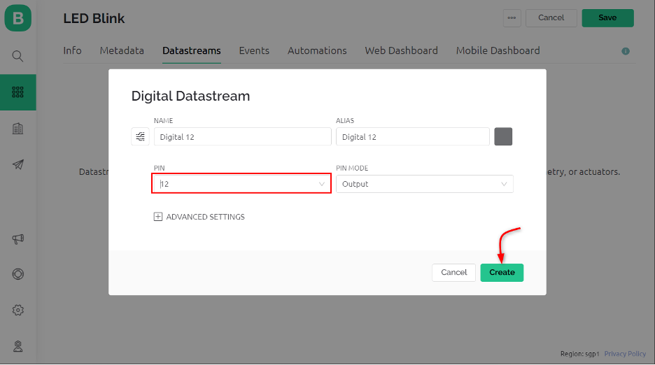
Step 8: Now select the pin at which the LED is connected. Here we used the D12 pin of ESP32 and configured it as an output:
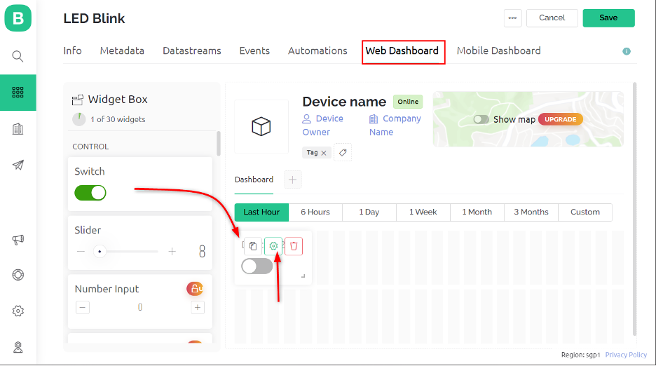
Step 9: To design a dashboard head towards the Web Dashboard menu. Drag and drop a new switch into the data stream:
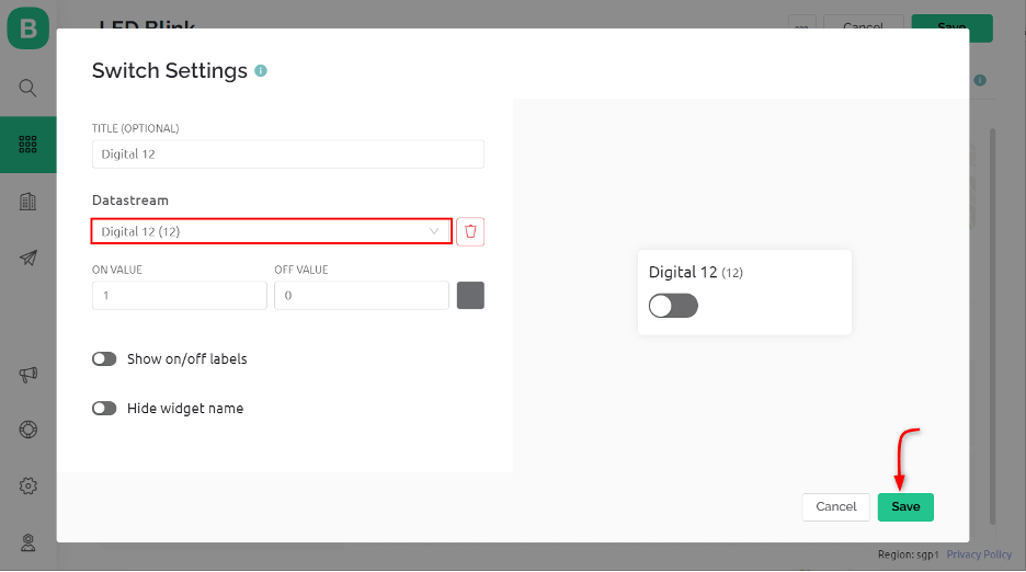
Step 10: After adding a new button now select the setting options. Here defined the DataStream source as Digital pin 12 and set ON value to 1 and OFF value to 0:
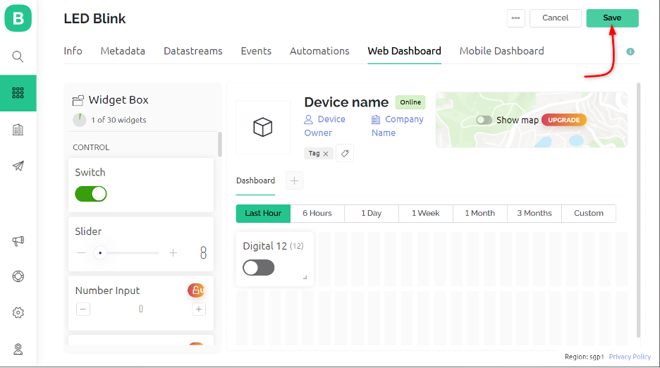
Step 11: After adding a new button save the settings. Using this method, we can add any switch that corresponds to a specific ESP32 pin:
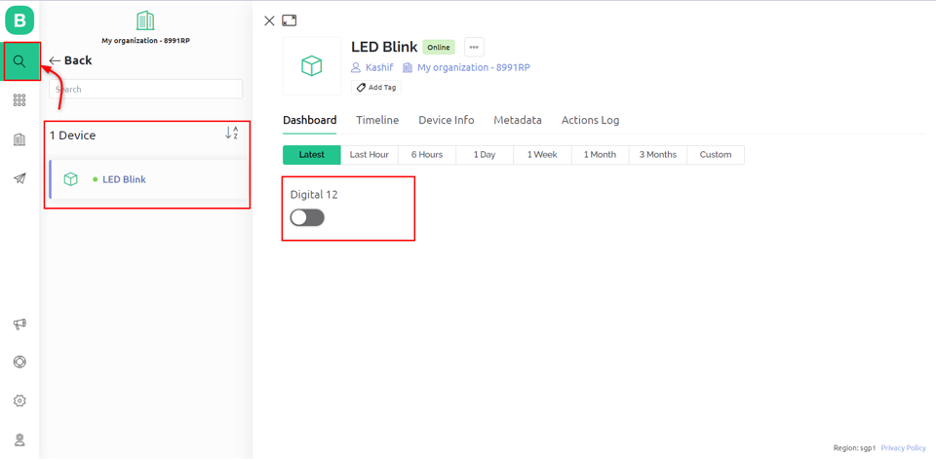
Step 12: Now to control LED using Blynk IoT, open the dashboard, here you can see a toggle switch to control LED connected at pin D12 of ESP32:
We have successfully created a control button for LEDs. Using this button, we can remotely control any appliance or device and sensor through ESP32 and Blynk IoT platform.
4: Designing LED Control GUI on Blynk Mobile Application
Like we added a button for LED control in Blynk IoT web dashboard. Similarly, we can also control the ESP32 using the Blynk IoT mobile application. One must make sure that both the Blynk Web and Mobile Application opened with the same account or email address.
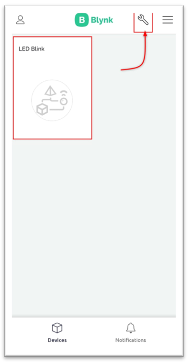
If you signed in with the same account, you would see the LED Blink project inside the Blynk IoT application. Open the developer mode using the setting icon on the top right corner:
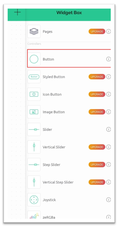
Here we can create new buttons for each pin across ESP32 or add a new one:
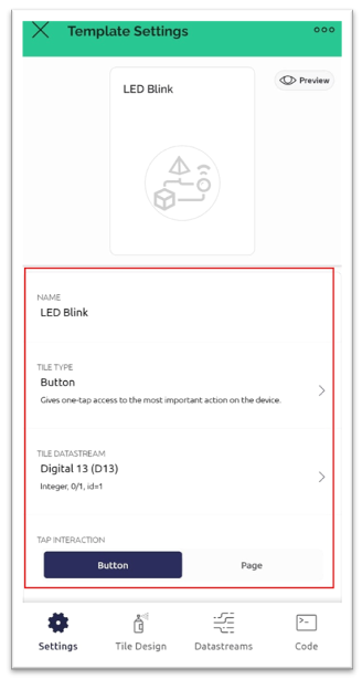
We can also adjust the settings inside the template such as pin number or switch working modes or set a new DataStream for the pin:
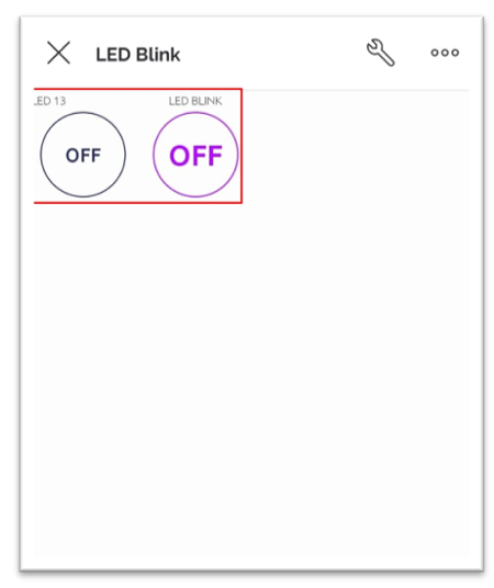
Similarly, we can add multiple buttons that can control different ESP32 pins:
5: Output
Once all settings are done toggle the switch D12 we can see the LED is turned ON connected to the D12 pin of the ESP32 board:
Conclusion
ESP32 paired with the Blynk app provides a powerful platform for creating internet-connected projects. With its rich set of features, the ESP32 enables developers to easily connect and control a variety of sensors and actuators, while the Blynk app provides a user-friendly interface for controlling and monitoring these devices from anywhere in the world.