How to Read ESP32 ADC Channels Using MicroPython
The ESP32 board has two integrated 12-bit ADCs also known as SAR (Successive Approximation Registers) ADCs. We can configure ESP32 ADCs using a MicroPython code. Just we need to install a Thonny IDE which is an editor for microcontrollers to program them using MicroPython.
Here are some prerequisites needed to program ESP32 using MicroPython:
- MicroPython firmware must be installed in ESP32 board
- Any IDE such as Thonny or uPyCraft is needed to program a code
The ESP32 board ADCs support 18 different analog input channels which means we can connect 18 different analog sensors to take input from them.
But this is not the case here; these analog channels are divided into two categories channel 1 and channel 2, both these channels have some pins that are not always available for ADC input. Let’s see what those ADC pins are along with others.
ESP32 ADC PIN
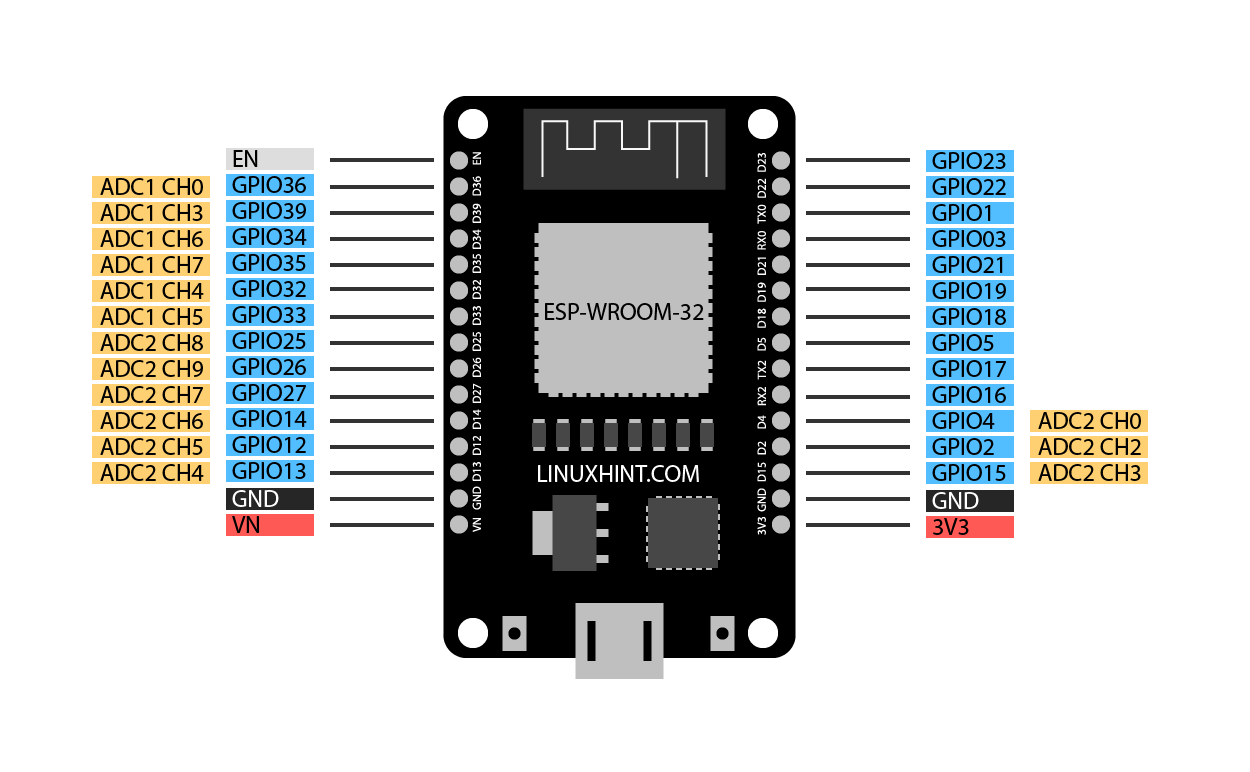
As mentioned earlier the ESP32 board has 18 ADC channels. Out of 18 only 15 are available in the DEVKIT V1 DOIT board having a total of 30 GPIOs.
Take a look on to your board and identify the ADC pins as we highlighted them in the image below:
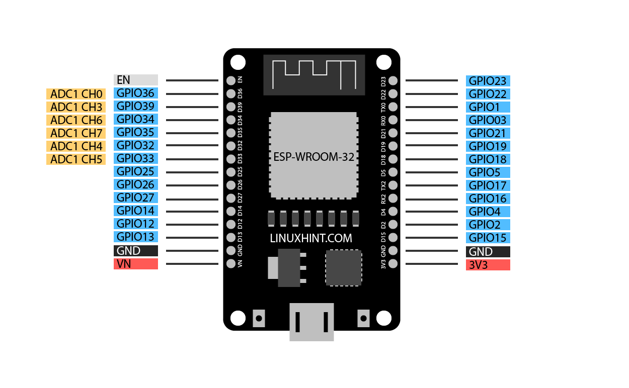
Channel 1 ADC Pin
Following is the given pin mapping of ESP32 DEVKIT DOIT board. ADC1 in ESP32 has 8 channels however the DOIT DEVKIT board only supports 6 channels. But I guarantee these are still more than enough.
| ADC1 | GPIO PIN ESP32 |
| CH0 | 36 |
| CH1 | NA in 30 pin version ESP32 (Devkit DOIT) |
| CH2 | NA |
| CH3 | 39 |
| CH4 | 32 |
| CH5 | 33 |
| CH6 | 34 |
| CH7 | 35 |
Following image show ESP32 ADC1 channels:
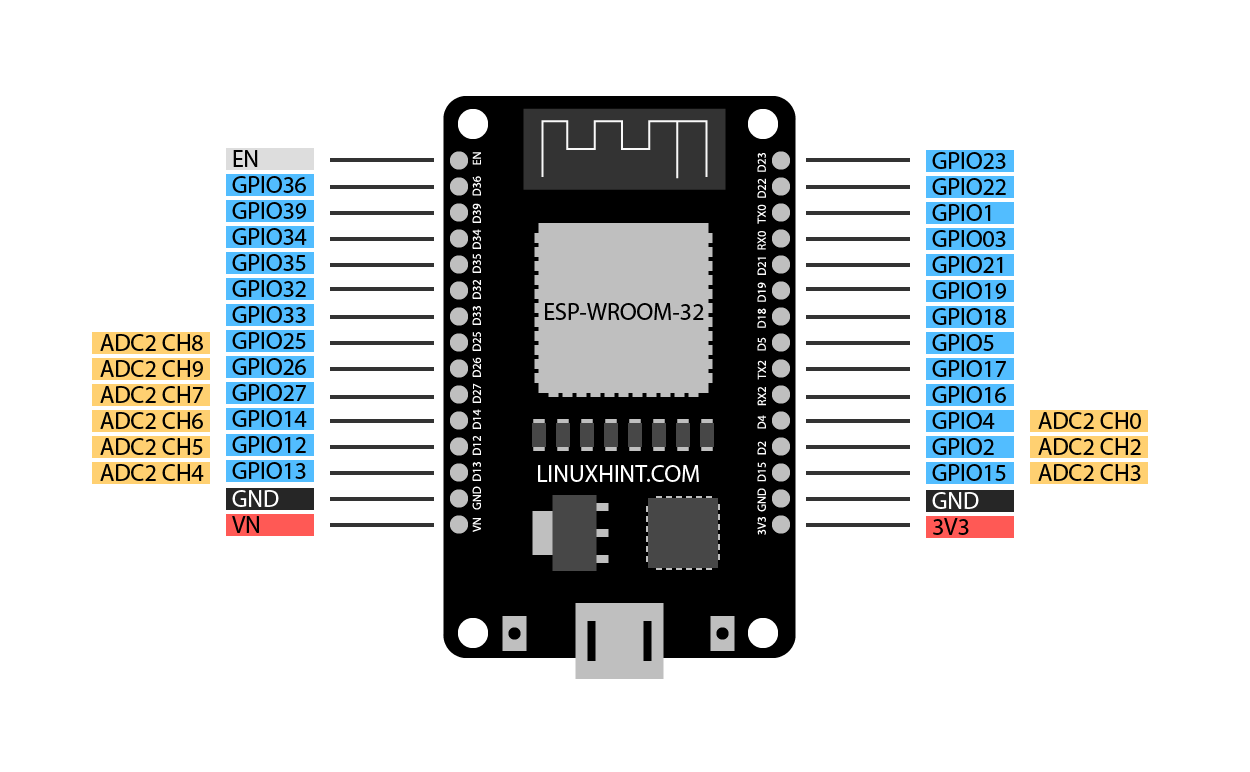
Channel 2 ADC Pin
DEVKIT DOIT boards have 10 analog channels in ADC2. Although ADC2 has 10 analog channels to read analog data, these channels are not always available to use. ADC2 is shared with onboard WiFi drivers, which means at the time the board is using WIFI these ADC2 will not be available. Quick fix is to use ADC2 only when the Wi-Fi driver is off.
| ADC2 | GPIO PIN ESP32 |
| CH0 | 4 |
| CH2 | 2 |
| CH3 | 15 |
| CH4 | 13 |
| CH5 | 12 |
| CH6 | 14 |
| CH7 | 27 |
| CH8 | 25 |
| CH9 | 26 |
Below image shows pin mapping of ADC2 channel.
How to Use ESP32 ADC
ESP32 ADC works similar to Arduino ADC. However ESP32 has 12-bit ADCs. So, the ESP32 board maps the analog voltage values ranging from 0 to 4095 in digital discrete values.
![]()
- If voltage given to ESP32 ADC is zero an ADC channel the digital value will be zero.
- If the voltage given to ADC is maximum means 3.3V the output digital value will be equal to 4095.
- To measure higher voltage, we can use the voltage divider method.
Note: ESP32 ADC is by default set at 12-bits, however it’s possible to configure it into 0-bit,10-bit, and 11-bit. The 12-bit default ADC can measure value 2^12=4096 and the analog voltage ranges from 0V to 3.3V.
ADC Limitation on ESP32
Here are some limitations of ESP32 ADC:
- ESP32 ADC cannot directly measure voltage greater than 3.3V.
- When Wi-Fi drivers are enabled ADC2 cannot be used. Only 8 channels of ADC1 can be used.
- The ESP32 ADC is not very linear; it shows non-linearity behavior and cannot distinguish between 3.2V and 3.3V. However, it is possible to calibrate ESP32 ADC. Here is a guide to calibrate ESP32 ADC nonlinearity behavior.
Nonlinearity behavior of ESP32 can be seen on the serial monitor of Arduino IDE.
How to Program ESP32 ADC Using Thonny IDE in MicroPython
Best way of understanding the working of ESP32 ADC is to take a potentiometer and read values against zero resistance to maximum. Following is the given circuit image of ESP32 with potentiometer.
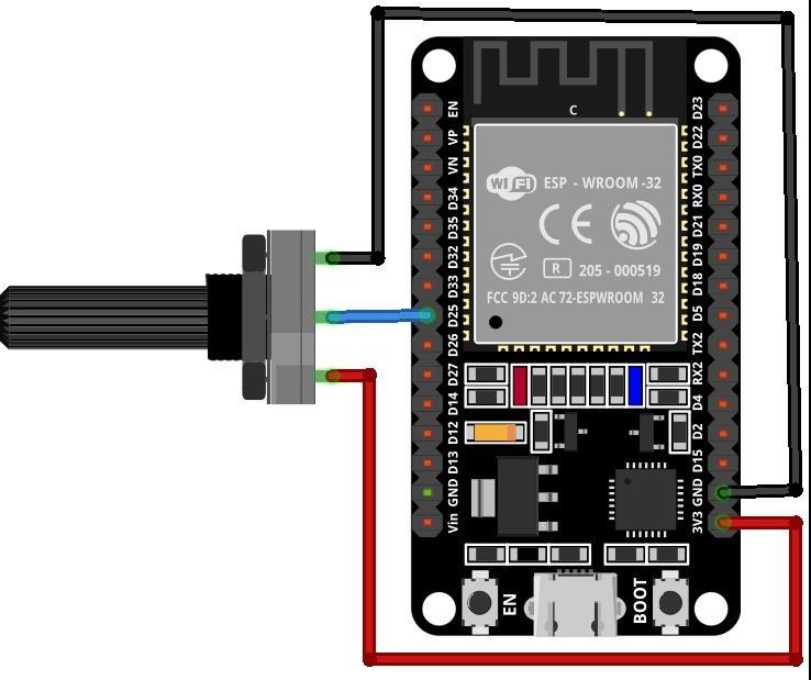
Connect the middle pin of potentiometer with digital pin 25 of ESP32 and 2 terminal pins with 3.3V and GND pin respectively.
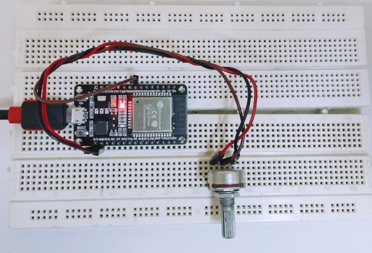
Hardware
Following image displays the hardware of ESP32 with potentiometer. Following is the list of components needed:
- ESP32 DEVKIT DOIT board
- Potentiometer
- Breadboard
- Jumper wires
Code
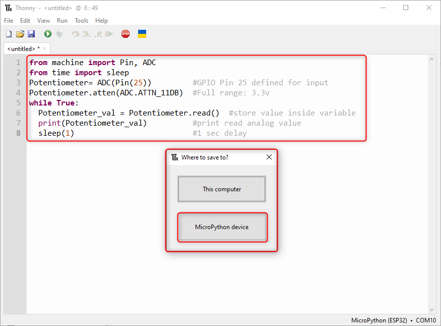
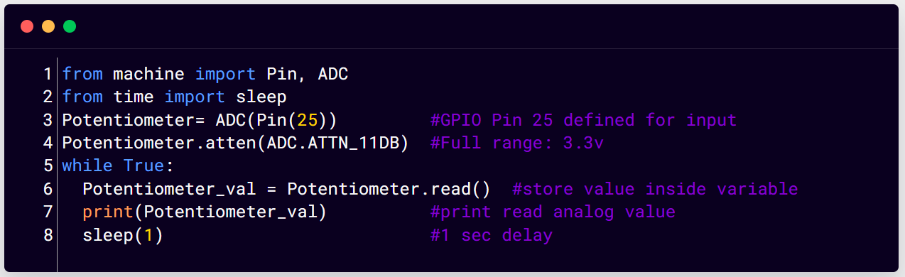
Open Thonny IDE and write the code given below in the editor window. Make sure the ESP32 board is connected to the PC. Now we have to save this code in the ESP32 board.
from time import sleep
Potentiometer= ADC(Pin(25)) #GPIO Pin 25 defined for input
Potentiometer.atten(ADC.ATTN_11DB) #Full range: 3.3v
while True:
Potentiometer_val = Potentiometer.read() #store value inside variable
print(Potentiometer_val) #print read analog value
sleep(1) #1 sec delay
In the case of programming ESP32 for the first time using MicroPython or Thonny IDE make sure the firmware is properly flashed inside ESP32 board.
Go to: File>Save or press Ctrl + S.
Following window will appear to save the file inside the MicroPython device.
Here in the given code we have to import three classes ADC, Pin, and sleep. Next, we created an ADC object pot at GPIO pin 25. After that we defined the range of ADC to read for its full 3.3V. Here we have set the attenuation ratio to 11db.
Following commands helps to set different ranges of ADC by defining the attenuation value:
- ADC.ATTN_0DB: Maximum voltage of 1.2V
- ADC.ATTN_2_5DB: Maximum voltage of 1.5V
- ADC.ATTN_6DB: Maximum voltage of 2.0V
- ADC.ATTN_11DB: Maximum voltage of 3.3V
Next, we read the value and store it inside the object Potentiometer_val. To print the read value print(Potentiometer_val) is used. A delay of 1 sec is given.
By default, ADC pins have 12-bit resolution, however the resolution of ADC is configurable if we want to measure any other voltage range. Using the ADC.width(bit) command we can define bits for ESP32 ADCs channels. Here bit argument can contain following parameters:
ADC.width(ADC.WIDTH_10BIT) //range from 0 to 1023
ADC.width(ADC.WIDTH_11BIT) //range from 0 to 2047
ADC.width(ADC.WIDTH_12BIT) //range from 0 to 4095
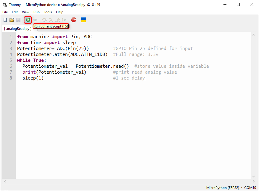
Once code is written, upload the code using the mentioned play green button on top of the window or press F5 to run the script.
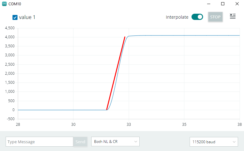
Output
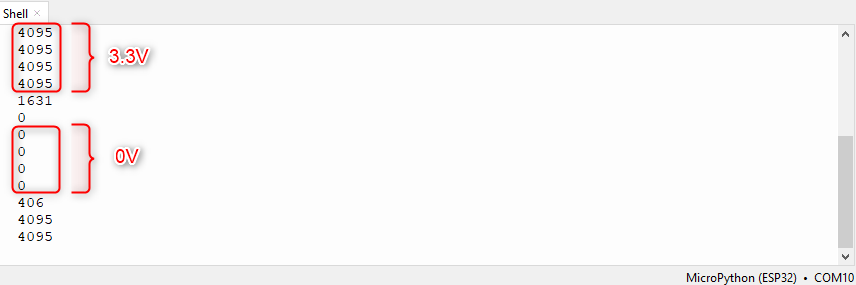
Output displays analog values mapped against digital discrete values. When the read voltage is maximum that is 3.3V digital output is equal to 4095 and when the read voltage is 0V the digital output becomes 0.
Conclusion
Analog to digital converters is used everywhere especially when we have to interface microcontroller boards with analog sensors and hardware. ESP32 has two channels for ADC that are ADC1 and ADC2. These two channels combine to provide 18 pins for interfacing analog sensors. However, 3 of them are not available on the ESP32 30 pin version. To see more about reading analog values read the article.