
ESP32 is an IoT based power conserving microcontroller board. ESP32 has all those features that a microcontroller board needs. It is a popular choice for Internet of Things (IoT) projects and is often used as a microcontroller for home automation, wearable electronics, and other connected devices. The ESP32 has a dual-core processor, many input/output (I/O) pins that can be programmed using the Arduino Integrated Development Environment (IDE). Today this article will cover steps needed to integrate an I2C OLED display with ESP32. After that we will draw a rectangular shape on an OLED screen.
This lesson includes following topics:
1: Introduction to ESP32 OLED Display
2: Wiring OLED Display Module to ESP32
3: Installing Required Libraries
4: Drawing a Rectangle on OLED Display Using Arduino IDE
5: Drawing a Filled Rectangle on OLED Screen Using Arduino IDE
6: Combining Both Rectangle on OLED Screen Using Arduino IDE
1: Introduction to ESP32 OLED Display
An I2C OLED display is a type of organic light-emitting diode (OLED) display that uses the Inter-Integrated Circuit (I2C) protocol for communication. OLED displays are known for their high contrast ratio, wide viewing angle, and fast response time, making them well-suited for a variety of display applications.
An I2C OLED display typically consists of a small OLED screen and a driver circuit that converts the I2C signals into the appropriate voltages and currents needed to drive the OLED pixels. These displays are often used in small portable devices such as smartwatches and fitness trackers, as well as in larger display panels and other applications where a compact, low-power display is required.
LEDs inside the OLED screen illuminate the pixels that display us different images and text. While on the other side the LCD screen uses a backlight for illuminating its pixels. Brightness of these pixels can be controlled pixel by pixel.
Now we will interface ESP32 with an OLED display.
2: Wiring OLED Display Module to ESP32
OLED screens mainly work on two communication protocols. These are I2C and SPI. Among these two SPI (Serial peripheral interface) is faster compared to I2C, but most of the time I2C OLED display is preferred because of a smaller number of wires.
I2C is a two-wire serial communication protocol that allows multiple devices to share a single set of data and clock lines, making it a convenient choice for connecting OLED displays to microcontrollers and other devices
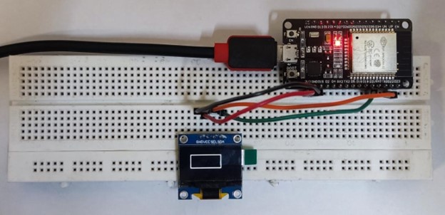
Using I2C OLED two pins SDA and SCL are enough for displaying images and text. The given image shows ESP32 with 0.96-inch (128×64 pixels) OLED screen:
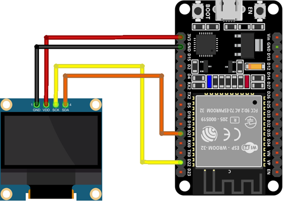
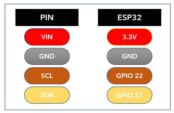
ESP32 pins connection with OLED is as follows:
As we have interfaced ESP32 with an OLED display, now we will install the necessary libraries in the Arduino IDE so we can move forward with shapes displaying on the OLED screen.
3: Installing Required Libraries
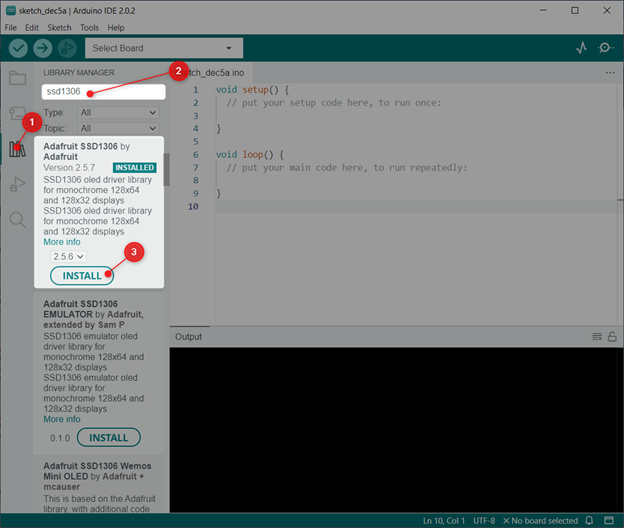
For displaying images, we need to install the necessary libraries for OLED display in Arduino IDE. Without using these libraries ESP32 cannot display graphics on OLED. Mainly two libraries from Adafruit are used: SSD1306 and GFX library.
First open the Arduino IDE and search the SSD1306 library. Install the SSD1306 OLED library by Adafruit. Other way of installing is going to: Sketch>Include Library>Manage Libraries:
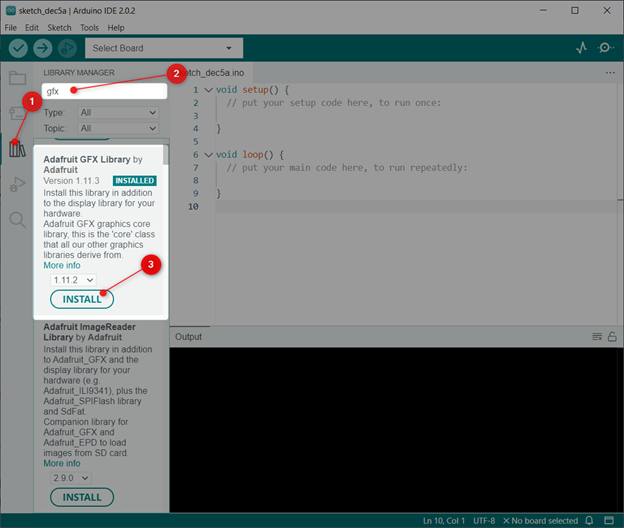
Now install the GFX library by Adafruit:
Now we have installed both libraries. Now we can easily program ESP32 with an OLED display.
4: Drawing a Rectangle on OLED Display Using Arduino IDE
To draw a rectangle on an OLED screen we will be using the drawRect(X-coordinate, Y-coordinate, Width, Height) function.
This function takes 4 arguments:
- Position of center with respect to x-coordinate
- Position of center with respect to y-coordinate
- Width of Rectangle
- Height of Rectangle
After defining all these three parameters, upload the code to the ESP32 board.
4.1: Code
Open Arduino IDE, connect ESP32 and upload code:
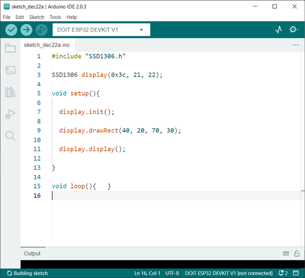
Code started by including the necessary SSD1306 library files. After that we defined the I2C address and the I2C pins for communication.
Remember to check the I2C address first before defining. For checking the I2C address of any device upload the code given in tutorial How to Scan I2C Address in ESP32 Using Arduino IDE.
If you are using more than one I2C device with the same address, you have to change the address of any of them first.
Next in code we initialized the OLED display and defined the drawRect() function. Here we defined the center pixel of the rectangle with x coordinate of 40 and y coordinate of 20. Width of the rectangle is set to 40 and Height of the rectangle is set to 30. Here both height and width of the rectangle is according to the number of pixels:
SSD1306 display(0x3c, 21, 22);
void setup(){
display.init();
display.drawRect(40, 20, 70, 30);
display.display();
}
void loop(){ }
4.2: Output
After uploading code in ESP32 below output will appear on the OLED screen:
5: Drawing a Filled Rectangle on OLED Screen Using Arduino IDE
Now we will draw a filled rectangle. Code is pretty much similar to the previous one. The only difference here is that we have used a new function display.fillRect(40, 20, 70, 30); this function also takes 4 arguments as the previous one. First two arguments will define the position of the rectangle and the remaining two will represent width and height of the rectangle respectively.
5.1: Code
Open Arduino IDE and upload the given code:

Code started by including the necessary SSD1306 library files. After that we defined the I2C address and the I2C pins for communication.
Next in code we initialized the OLED display and defined the fillRect() function as a filled rectangle. This function will draw a filled rectangle with defined parameters. Here we defined the center pixel of the rectangle with x coordinate of 40 and y coordinate of 20. Rectangle with width and height of 70 and 30 respectively will draw on an OLED screen.
SSD1306 display(0x3c, 21, 22);
void setup(){
display.init();
display.fillRect(40, 20, 70, 30);
display.display();
}
void loop(){ }
5.2: Output
After uploading code to ESP32 below the filled rectangle can be seen:

6: Combining Both Rectangles on OLED Screen Using Arduino IDE
Now to combine both rectangles we will define both functions in the same program. Remember to change the position and dimensions of the rectangle otherwise both rectangles will overlap.
6.1: Code
Open Arduino IDE and upload code to ESP32:
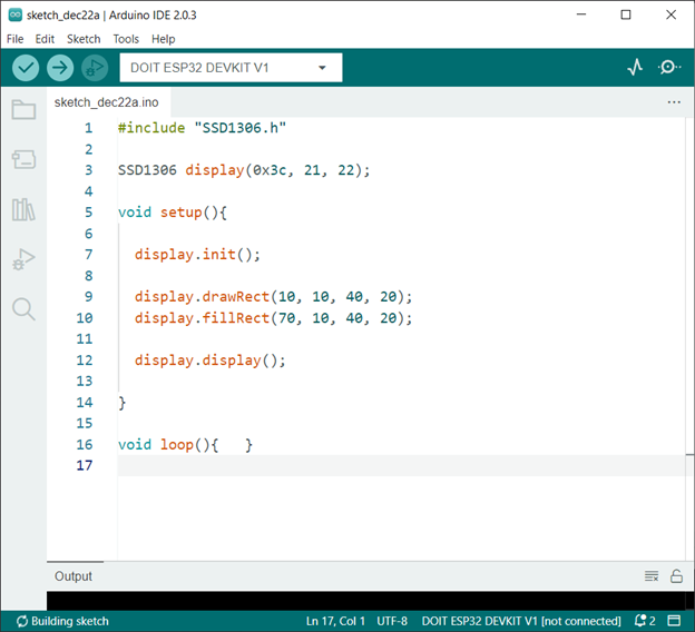
This program will draw two rectangles with the same dimensions. One rectangle is filled and the other one is unfilled.
SSD1306 display(0x3c, 21, 22);
void setup(){
display.init();
display.drawRect(10, 10, 40, 20);
display.fillRect(70, 10, 40, 20);
display.display();
}
void loop(){ }
6.2: Output
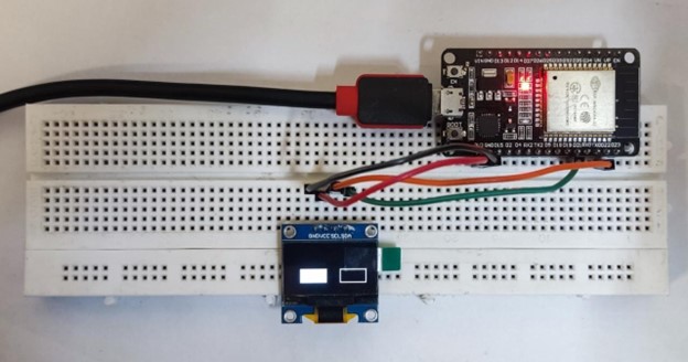
After uploading code, we can see the output below on the OLED screen:
Conclusion
OLED displays are a great way of giving a graphical representation to our data. Here this article covers some simple steps needed to draw a rectangle on an OLED screen. Using the given code any OLED display can be used to display images and text.