ESP32 boards have a built-in Wi-Fi module which opens the door to unlimited connectivity options. ESP32 can be connected to any access point such as a router or can act as a hotspot and provide an access point to other devices. Here we will set up ESP32 in access point mode and connect it with other devices.
ESP32 WiFi Modes
Before we move forward, we must have knowledge of ESP32 WiFi working modes. ESP32 WiFi can be used in three different modes.
- Station
- Access Point
- Station + Access Point
Following modes can be called using the WiFi.mode() function by defining the desired mode inside the argument of this function.
| WiFi Mode | Function |
| Station | WiFi.mode(WIFI_STA) |
| Access Point | WiFi.mode(WIFI_AP) |
| Station + Access Point | WiFi.mode(WIFI_STA_AP) |
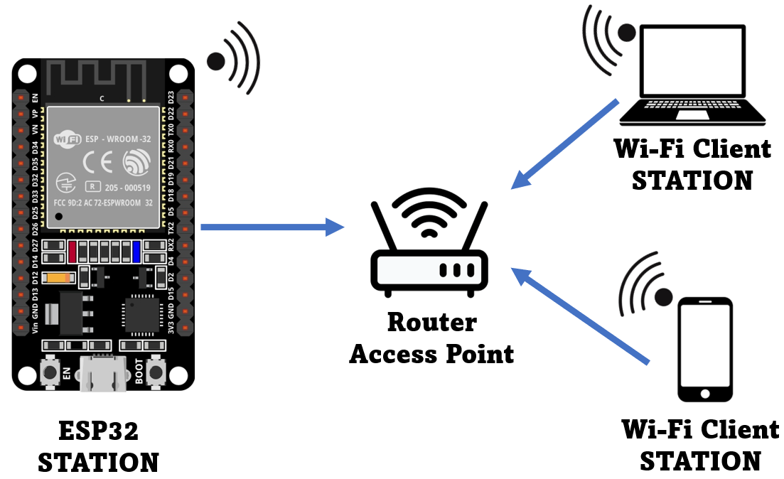
In most of the situations ESP32 works in Station mode. During this mode ESP32 is connected to WiFi of any access point such as the router. Following image shows ESP32 in station mode connected to the router which is an access point.
But we can also use ESP32 WiFi to work as hotspots for other devices. In short using the WiFi.mode(WIFI_AP) command we will be using ESP32 as an Access point where it will create its own WiFi network. Now any device with WiFi capabilities can connect to it.
The below given image demonstrates the working of ESP32 as an access point for other devices.

As the ESP32 board doesn’t have wired network capability it only supports wireless networks, so we called this access point as Soft-AP (Soft Access Point).
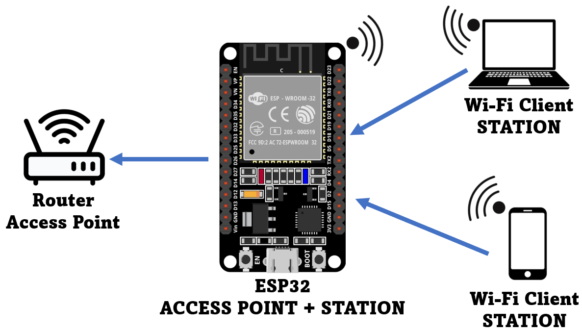
Last mode of WiFi for the ESP32 board is both Access and Station point. Here the ESP32 board will be connected to some other router and will act as a station while it also advertises its hotspot to other devices so they can connect to ESP32 Wi-Fi.
Image given below highlights the structure of ESP32 board working in both station and access point.
How to Connect ESP32 Board as an Access Point
Connect ESP32 board with PC and open Arduino IDE. Select the right board and COM port. Open the IDE editor and write given code. This code will enable ESP32 WiFi which will work in access point mode.
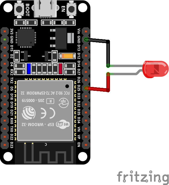
Now connect a LED to GPIO pin 25. We will control this LED using a web server designed on the IP address of ESP32 board. A WiFi device such as a PC or Smartphone will be connected to the WiFi of ESP32 and control LED using the web server.
ESP32 Access Point Code
Now upload the code given below to ESP32 board:
const char* ssid = "ESP32"; /*SSID defined for AP*/
const char* password = "123456789"; /*Password defined, removed for an open network*/
WiFiServer server(80); /*Web Server Port 80*/
String header; /*variable stores HTTP request*/
String OutputGPIO25 = "OFF"; /*variable to store current Output*/
const int Output_25 = 25; /*GPIO pin 25 assigned to variable*/
void setup() {
Serial.begin(115200);
pinMode(Output_25, OUTPUT); /*variable initialize for output*/
digitalWrite(Output_25, LOW); /*Output set to low*/
Serial.print("Setting AP (Access Point)…");
WiFi.softAP(ssid, password); /*ESP32 wifi set in Access Point mode*/
IPAddress IP = WiFi.softAPIP(); /*IP address is initialized*/
Serial.print("AP IP address: ");
Serial.println(IP); /*Print IP address*/
server.begin();
}
void loop(){
WiFiClient client = server.available(); /*check for clients request*/
if (client) { /*Condition to check for new client*/
Serial.println("New Client.");
String currentLine = ""; /*string to hold data*/
while (client.connected()) { /*loop for client connection check*/
if (client.available()) { /*read if data available*/
char c = client.read();
Serial.write(c);
header += c;
if (c == '\n') { /*if byte is newline character*/
/*in case if current line is blank two new line characters will be available*/
/*end of client hTTP request*/
if (currentLine.length() == 0) {
/* HTTP start with a response code HTTP/1.1 200 OK */
/* and content-type so client knows what's coming, then a blank line:*/
client.println("HTTP/1.1 200 OK");
client.println("Content-type:text/html");
client.println("Connection: close");
client.println();
/*turns the GPIOs 25 ON and OFF*/
if (header.indexOf("GET /25/ON") >= 0) {
Serial.println("GPIO 25 ON");
OutputGPIO25 = "ON";
digitalWrite(Output_25, HIGH);
} else if (header.indexOf("GET /25/OFF") >= 0) {
Serial.println("GPIO 25 OFF");
OutputGPIO25 = "OFF";
digitalWrite(Output_25, LOW);
}
/*HTML code for server*/
client.println("");
client.println("");
client.println("");
/*including CSS to customize button*/
client.println("html { background-color: #c4ccc8; font-family: Fantasy; display: inline-block; margin: 0px auto; text-align: center;}");
client.println(".button { background-color: #000000; display: inline-block; border-radius: 30px;border: 2px solid gray; color: white; padding: 16px 40px;");
client.println("text-decoration: none; font-size: 30px; margin: 2px; cursor: pointer;}");
client.println(".button2 {background-color: #f70d05;}");
/*Web page headings*/
client.println("<h1>Web Server ESP32</h1>");
client.println("<h1>Linuxhint.com</h1>");
// Display current state, and ON/OFF buttons for GPIO 25
client.println("<p>GPIO 25 LED " + OutputGPIO25 + "</p>");
// If the OutputGPIO25 is OFF, it displays the ON button
if (OutputGPIO25=="OFF") {
client.println("<p><a href="/25/ON"><button class="button">ON</button></a></p>");
} else {
client.println("<p><a href="/25/OFF"><button class="button button2">OFF</button></a></p>");
}
client.println("");
/*HTTP response end with blank line*/
client.println();
/*while loop break*/
break;
} else { /*in new line clear current line*/
currentLine = "";
}
} else if (c != '\r') { /*a carriage return character*/
currentLine += c; /*add to the end of currentLine*/
}
}
}
/*clear header*/
header = "";
client.stop(); /*client disconnected*/
Serial.println("Client disconnected.");
Serial.println("");
}
}
Code starts by defining the SSID and password for the Access point network. You can customize both SSID and password according to the given requirement.
In the above code we defined a LED as output at GPIO pin 25 and using the HTML and CSS code we designed a control button for the LED.
Next using the command WiFi.softAP(ssid, password); we set up ESP32 as an access point. Some optional parameters are there which one can modify according to need.
- ssid: Define Access point (max 63 characters)
- password: Password of Access point (min 8 characters)
- channel: Wi-Fi channels (1-13)
- ssid_hidden: 0 for broadcasting SSID and 1 for hiding SSID
- max_connection: maximum client can be connected (1-4)
Next using the function softAPIP() we get the IP address and print it on the serial monitor.
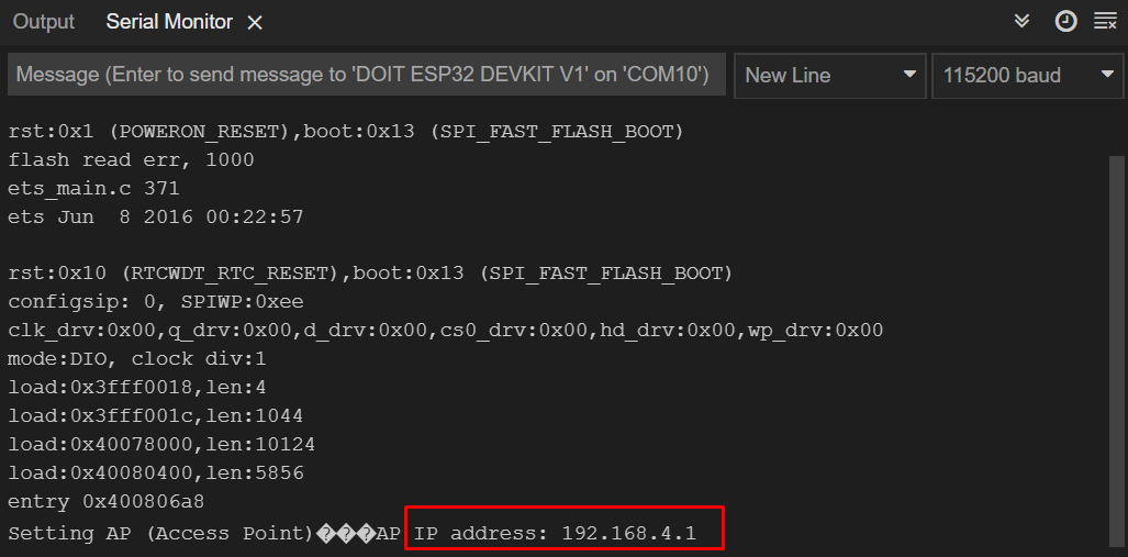
Output
Once code is uploaded the result will display on the serial monitor. Here ESP32 will provide us with an IP address. The IP address given by ESP32 is 192.168.4.1 Using this IP we can access the web server.
How to Connect Devices to ESP32 Access Point
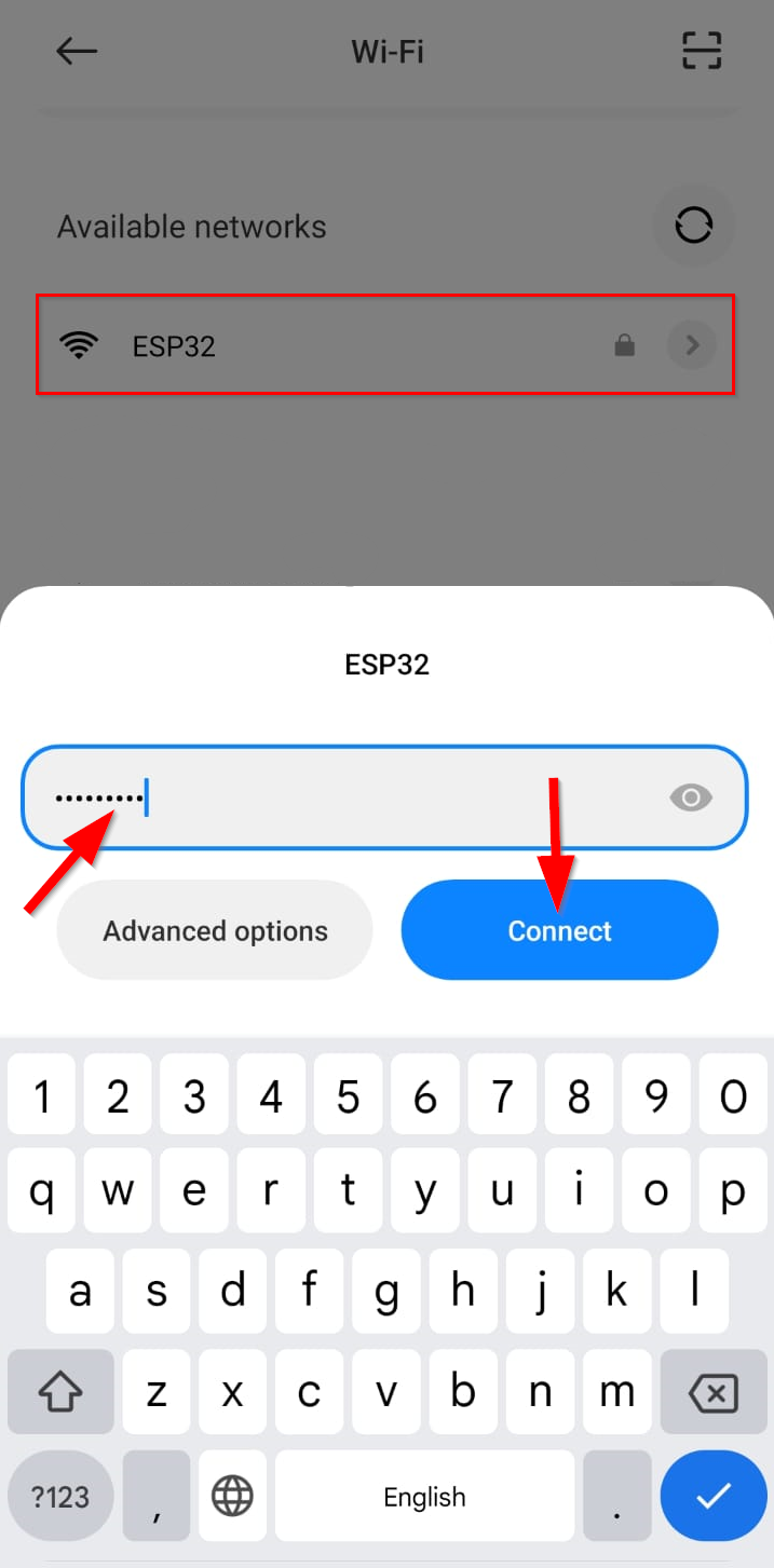
First, we will connect a smartphone with an ESP32 access point. Go to the WiFi settings of the smartphone connected to the ESP32 board by typing the password defined in code.
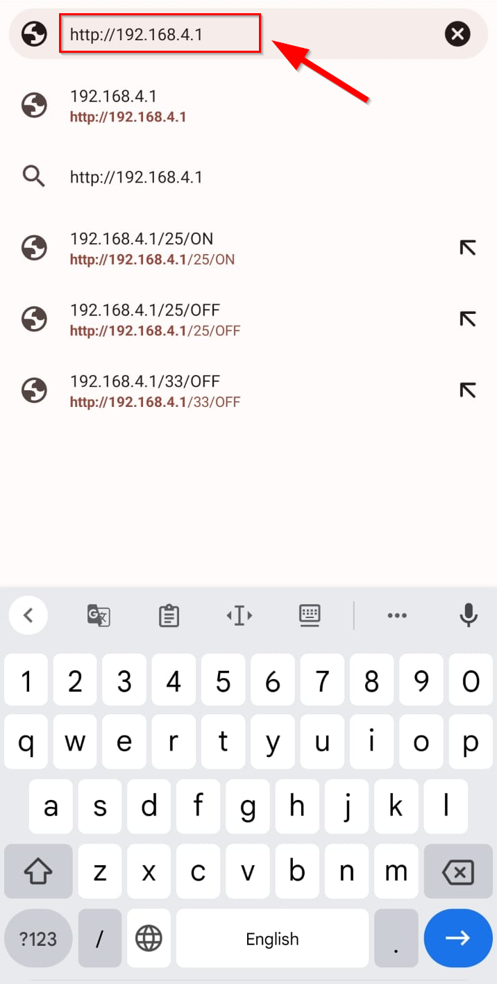
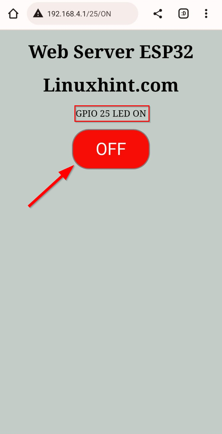
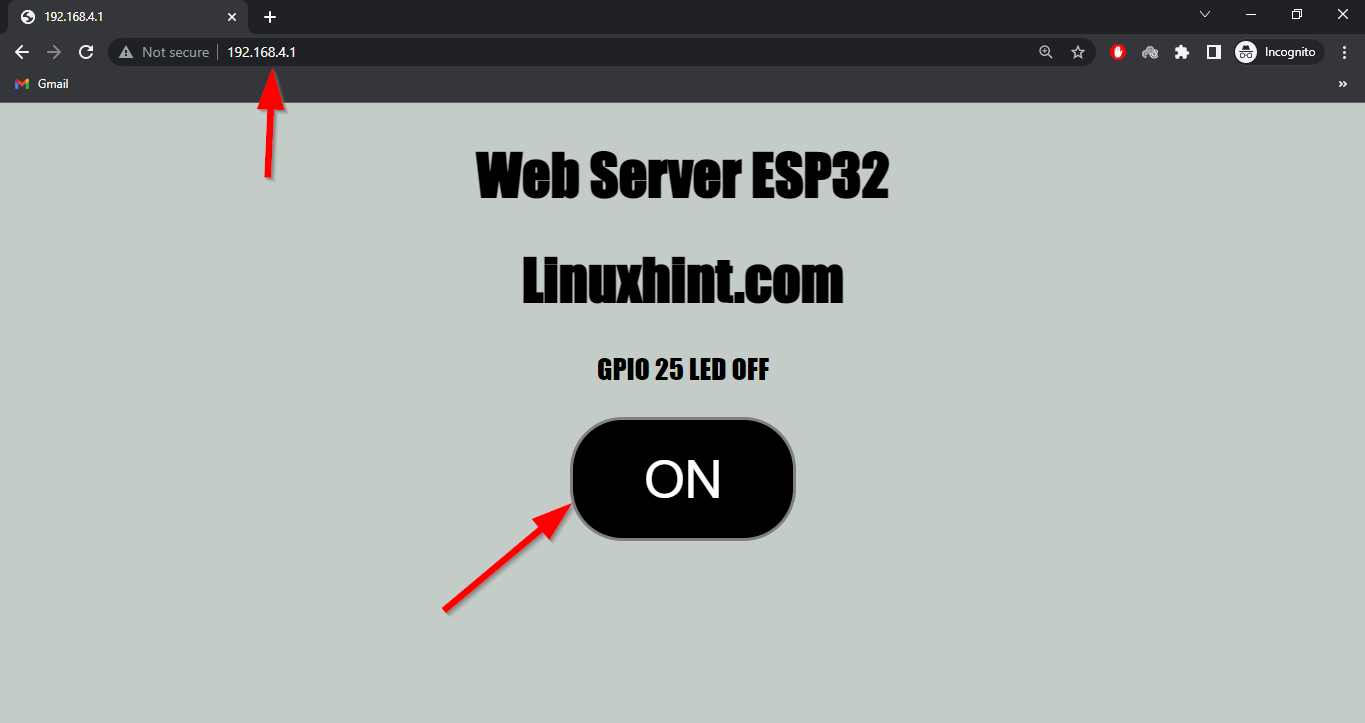
Once the ESP32 is connected, open any browser, and enter the IP address (192.168.4.1) of ESP32 board and press enter.
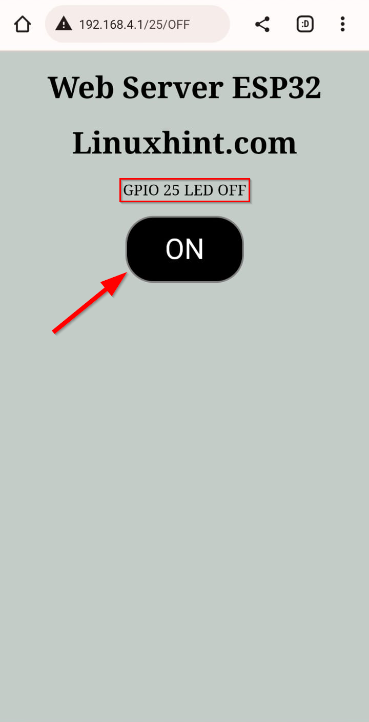
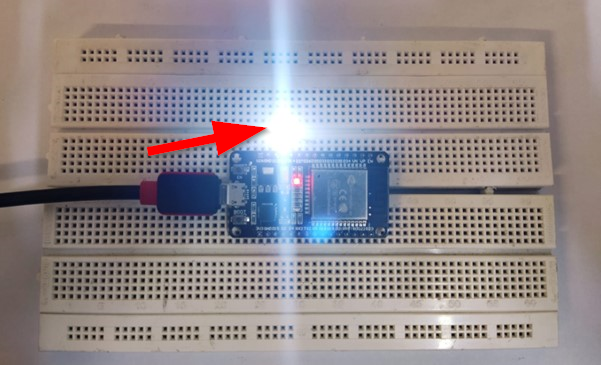
Turn ON LED
Following tab will open in the browser. Which shows the interface of ESP32 web server. Currently the LED status is OFF, click ON button to light the LED.
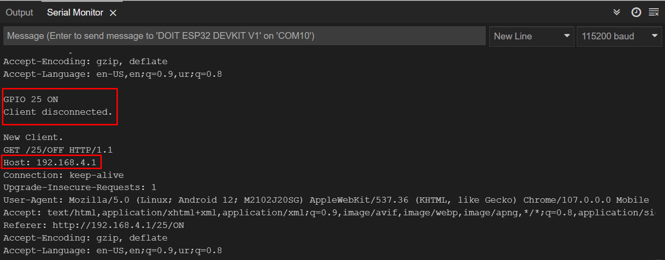
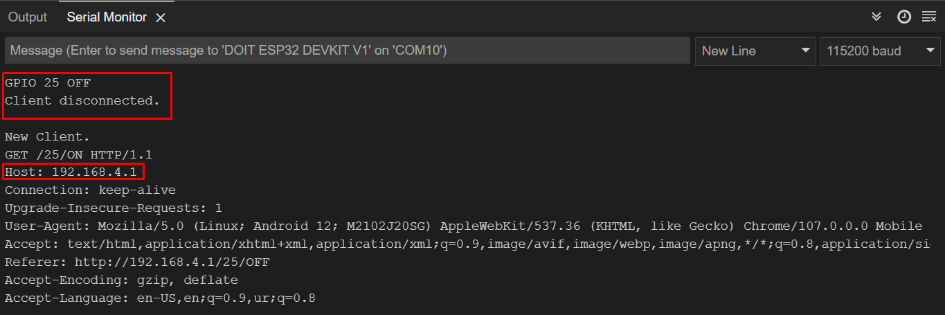
Once the LED button is pressed the output can be read on the serial monitor showing us the GPIO pin status.
On hardware we can see that the LED is turned on connected at GPIO 25.
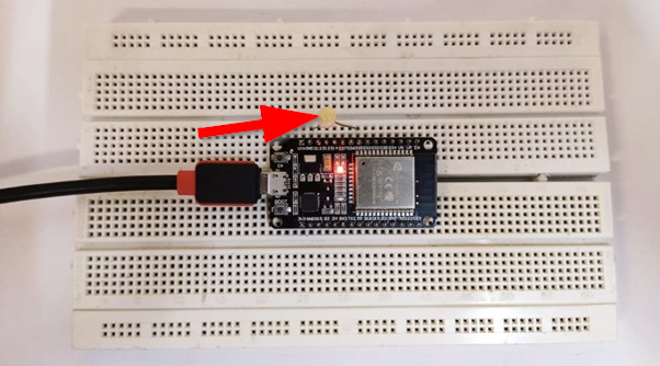
Turn OFF LED
Now to turn OFF the LED again press the OFF button. This time the LED will turn OFF and GPIO pin status will change to OFF.
Following output will be displayed on the serial monitor; we can see the LED status at GPIO pin 25.
On hardware we can see the LED is turned OFF.
How to Connect ESP32 Access Point with PC
Just like we did in smartphones, the same procedure will be followed to connect the PC with ESP32 access point. Open the wifi setting using the task bar and click the ESP32 WiFi.
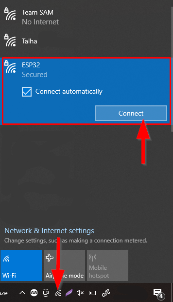
Now type the password for SSID defined in code and click next. The PC will connect itself to the ESP32 access point.

Now open a browser type IP address in the URL bar of the ESP32 board. Following tab will open showing us a similar interface like we did in smartphones.
We have successfully operated ESP32 in access mode and control an LED using the web server.
Conclusion
ESP32 board WiFi operates in three different modes: station and access mode or can be used both modes simultaneously. Here we have enabled ESP32 in access mode and connected different devices with it. Finally, we controlled a LED using the web server designed on the IP address of ESP32. Using this article any one can connect ESP32 board in access point mode and operate it as a hotspot device.