
What is a PWM
The PWM is known as the pulse width modulation which is used to control the power of the continuous electrical signal by switching it in between the HIGH and LOW by a specific time. With the help of the PWM technique, we can control various devices.
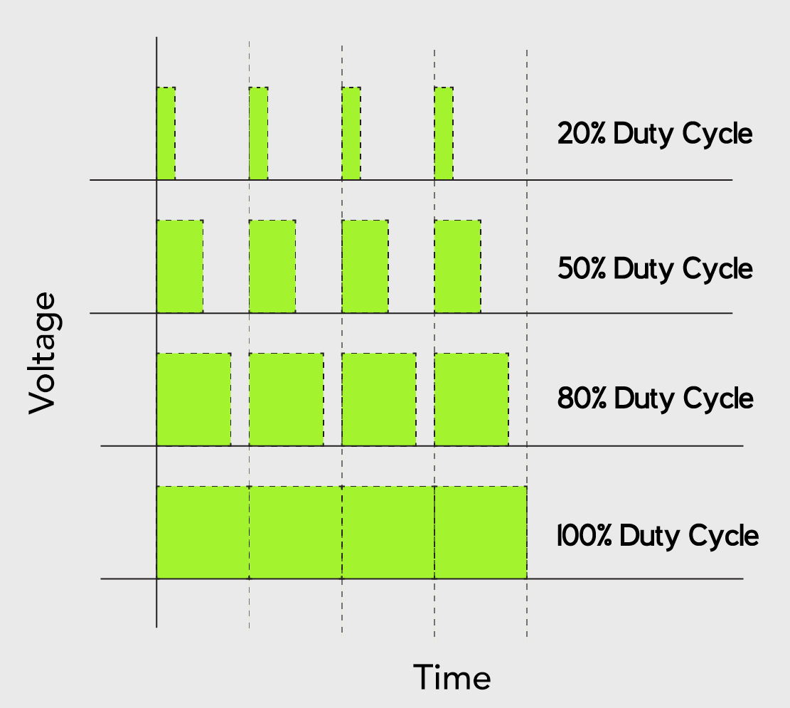
By changing the duty cycle PWM can be controlled.
How to generate a PWM using the Raspberry Pi 4
As we discussed above, the Raspberry Pi 4 has two PWM channels which consist of four PWM GPIO pins which are GPIO12, GPIO13, GPIO18, and GPIO19. We will understand the generation and working of the PWM in Raspberry Pi 4 by making a simple electrical circuit to fade the brightness of the LED. The change of brightness of the LED is done by providing a continuous or analogue electrical signal to the LED which we will provide by using the PWM pins of Raspberry Pi 4.
How to fade a LED by PWM technique in the Raspberry Pi 4
For the circuit, to fade the LED we need the following electronic components:
- LED
- 1 Resistor
- Breadboard
- Jumper wires
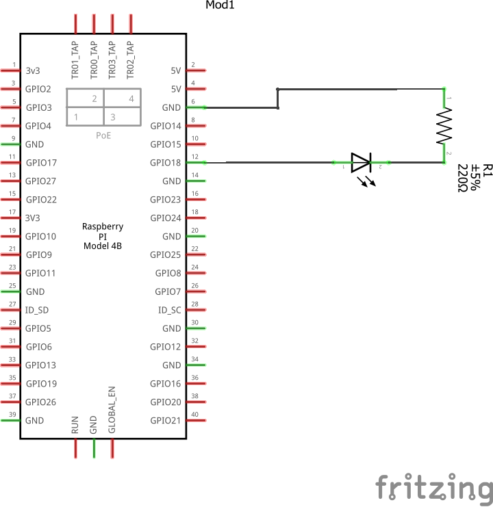
The circuit diagram for the circuit to fade the LED will be:
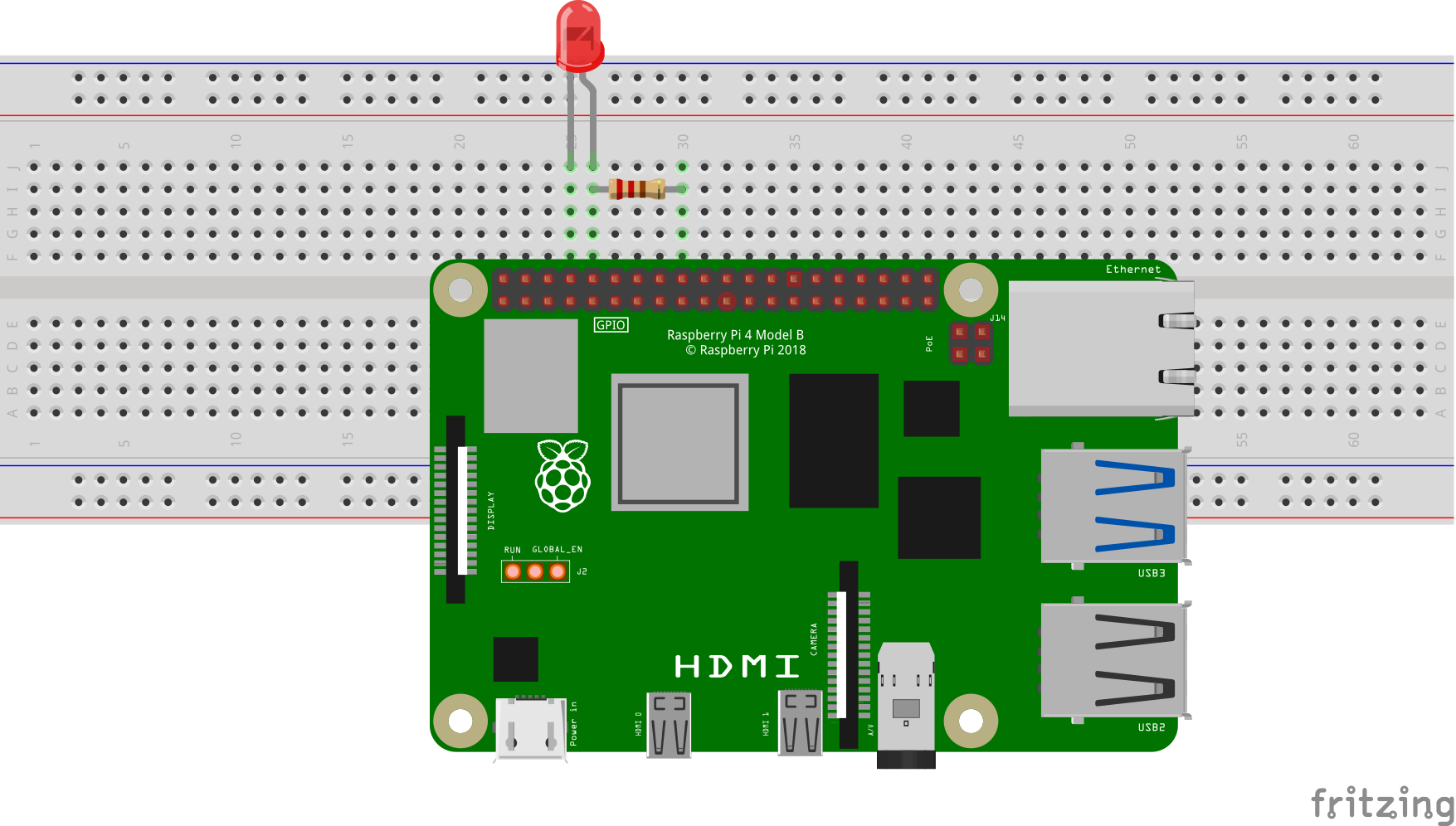
For the implementation of the above circuit, we will place all the components on the breadboard:
Now we will connect the cathode of the LED with the Ground pin of Raspberry pi and open the terminal of the resistor (its other terminal is connected with the anode of the LED) to the GPIO 18 pin of the Raspberry Pi 4 using the jumper wires:
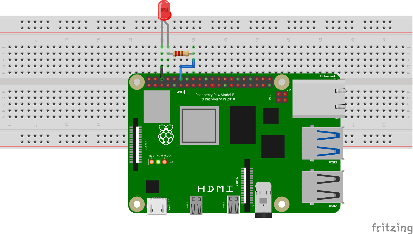
The circuit is completed.
What is the Python code to fade the LED with PWM technique using the Raspberry Pi 4
We will open the text file with the name of “fade.py” using the nano text editor:
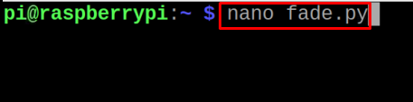
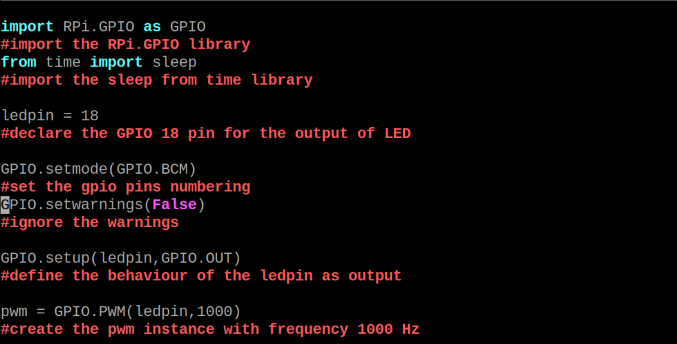
Type the following python script in the file:
#import the RPi.GPIO library
from time import sleep
#import the sleep from time library
ledpin = 18
#declare the GPIO 18 pin for the output of LED
GPIO.setup(ledpin,GPIO.OUT)
#define the behaviour of the ledpin as output
GPIO.setwarnings(False)
#ignore the warnings
pwm = GPIO.PWM(ledpin,1000)
#create the pwm instance with frequency 1000 Hz
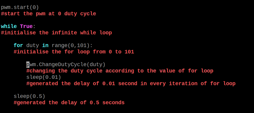
pwm.start(0)
#start the pwm at 0 duty cycle
while True:
#initialise the infinite while loop
for duty in range(0,101):
#initialise the for loop
pwm.ChangeDutyCycle(duty)
#changing the duty cycle according to the value of for loop
sleep(0.01)
#generated the delay of 0.01 second in every iteration of for loop
sleep(0.5)
#generated the delay of 0.5 seconds
for duty in range(100,-1,-1):
#again started the for loop be setting its value of 100 and decremented by -1 till -1
pwm.ChangeDutyCycle(duty)
#changing the duty cycle according to the value of for loop
sleep(0.01)
#generated the delay of 0.01 second in every iteration of for loop
sleep(0.5)
#generated the delay of 0.5 second
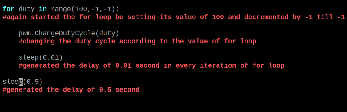
Explanation of code: In the above Python code, we have imported two libraries of RPi.GPIO and sleep from time. Then we declare the ledpin variable and assign it the GPIO 18 pin, also defining it as a PWM pin. We started the PWM instance at 0 frequency, then defined the range of 0 to 101 and in the for loops changing the duty cycle. In the first for loop, by changing the duty cycle from 0 to 101, we are increasing the brightness and in the second for loop, by changing the duty cycle from 100 to -1, we are decreasing the brightness of the LED. Both for loops are in the body of an infinite while loop, so this process will continue repeatedly for an infinite time.
To compile and run the Python script of the fade.py, we will use the command:

The hardware working of the circuit is:

Conclusion
The PWM technique in the microcontrollers is very useful to control the continuous or analog output. To fade the LED using the PWM technique is the best example to explain the working of the PWM technique. The duty cycle is changing from 0 to 100 percent making the LED fades in and fades out. In this write-up, we have explained the generation of the PWM by giving an example of an electronic circuit of fading the LED.