What is a Harley Oscillator?
The Harley oscillator is a type of electronic oscillator that generates continuous sine wave signals at a specific frequency. Operating on the principle of feedback, the oscillator sustains oscillation by feeding back a portion of the output signal to the input. The Harley oscillator finds extensive use in telecommunications, radio frequency (RF) applications, and audio equipment.
How Does a Harley Oscillator Work?
The Harley oscillator comprises an active device, usually a vacuum tube or transistor, and a passive LC (inductor-capacitor) tank circuit. The oscillator’s working principle revolves around achieving resonance in the LC tank circuit, which allows sustained oscillation at the desired frequency.
The tank circuit consists of an inductor (L) and a capacitor (C) connected in parallel and the active device, such as a transistor, is connected in a feedback configuration with the tank circuit. The feedback network in the oscillator comprises a resistor (R) and a capacitive voltage divider.
During operation, the active device amplifies the small signal generated by the feedback network and feeds it back into the tank circuit. This feedback reinforces the oscillation and maintains it at the desired frequency. The oscillation frequency in the circuit is determined by the values of the inductor and capacitor in the tank circuit.
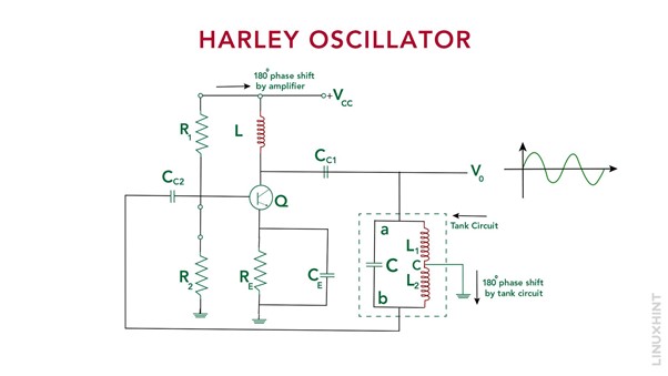
In the given circuit, various elements serve specific purposes. For biasing, resistors R1, R2, and RE are utilized, while CC1 and CC2 serve as coupling capacitors. An RFC acts as a radio frequency choke coil, offering high reactance in high-frequency applications. It isolates AC and DC conditions. The transistor amplifier provides a 180⁰ phase shift. The tank circuit, composed of L1, L2, and C, generates damped oscillations. Amplification is necessary to prevent oscillation decay. The common emitter configuration transistor amplifies the input signal. Feedback energy is supplied by the mutual inductance between L2 and L1. The amplified output sustains the sinusoidal oscillations in the tank circuit, compensating for losses.
Types of Harley Oscillators
1. Series Fed Harley Oscillator
In the series-fed Harley oscillator, the tank circuit is connected in series with the active device. This means that the tank circuit components (L and C) are positioned between the power supply and the active device. The series-fed configuration provides high voltage gain, making it suitable for applications that require high-power output.
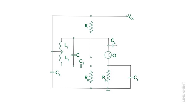
The provided diagram illustrates the series-fed Hartley oscillator and, like its shunt-fed counterpart, the base circuit is biased using a voltage divider and stabilized with an emitter. The tap on the tank inductor is used to apply the collector voltage, while C3 serves as a shunt to route the signal from the voltage source.
The operation of the series-fed circuit is essentially the same as the previously discussed shunt-fed circuit. However, due to the presence of a DC current flowing through a section of the tank circuit, the Q factor is reduced, leading to lower frequency stability compared to the shunt-fed circuit.
2. Shunt Fed Harley Oscillator
In the shunt-fed Harley oscillator, the tank circuit is connected in parallel with the active device. Here, the tank circuit components are placed in parallel with the power supply and the active device. The shunt-fed configuration is well-suited for low-power applications due to its superior frequency stability and low power consumption.
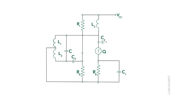
The provided diagram illustrates the shunt-fed Hartley oscillator using the common-emitter configuration. Fixed bias is achieved through voltage-dividing resistors R1 and RB, while temperature stabilization is ensured by emitter-swamping resistor RE, bypassed with C1. The collector is shunt-fed via inductor L3, with C3 serving as a DC blocking and coupling capacitor to prevent shorting. Similarly, C2 acts as a base-blocking coupling capacitor, preventing base-to-ground shorting through the tank inductor.
Initial bias is set by R1 and RB when the shunt-fed circuit is powered, and oscillation is created via feedback from the collector to the base via sections L1 and L2 of the tank inductor.
AC paths are formed from the emitter through L1 and C3 to the collector, as well as from L2 and C2 to the base.
Oscillation generates a degenerative bias across RE (with the appropriate C1 value). R1 and RB are typically chosen for Class A bias to facilitate starting, while RE and C1 values provide thermal stabilization and desired Class B or C bias for operational efficiency.
Frequency of Oscillations in Harley Oscillator
The frequency of oscillations for the sinusoidal signal produced by the tank circuit can be determined using the following expression:
In the Hartley oscillator, the tank circuit consists of two inductors. As a result, the equivalent inductance of the tank circuit can be calculated as follows:
When calculating the equivalent inductance in the Hartley oscillator, it is important to account for the mutual inductance between the coils. Therefore, the mutual inductance factor should be considered to accurately determine the overall equivalent inductance of the circuit:
Consequently, the oscillation frequency can be determined by using the following expression:

Conclusion
The Harley oscillator is an essential electronic component known for its ability to generate continuous sine wave signals at a specific frequency. Knowing its working principle and the two types (series fed and shunt fed), you can apply this knowledge to various applications in telecommunications, RF systems, audio equipment, and test and measurement instruments. Harnessing the power of the Harley oscillator allows for reliable and accurate signal generation in a wide range of electronic systems.


