voltage multiplier is an electrical circuit that provides multiples of input voltage at its output. The input voltage is AC while the output appears as DC voltage in voltage multiplier circuits. They are composed of capacitor and diode combinations and their cascades to generate voltage doublers, tripler, and quadruples. This article discusses voltage multipliers in detail.
Voltage Multiplier
A voltage multiplier is an electronic circuit that increases the voltage of a signal. It is commonly used in various applications. The Voltage Multiplier is a diode rectifier circuit that is capable of producing output voltage that is quite higher than the applied voltage.
The Voltage Multiplier is a diode-based rectifier circuit that has the capability of producing an output voltage that is significantly higher than the input voltage.
Why Use Voltage Multipliers?
Step-up transformers can easily amplify voltage levels. However, there are instances where a viable step-up transformer or an appropriately insulated transformer for high-voltage applications may not be readily accessible. An alternate methodology involves the utilization of a diode voltage multiplier circuit, which facilitates the amplification or “stepping up” of voltage without the necessity of a transformer.
Full Wave Voltage Multiplier
The full wave voltage multiplier increases the voltage level of the applied voltage. It operates by utilizing the full-wave rectification technique.
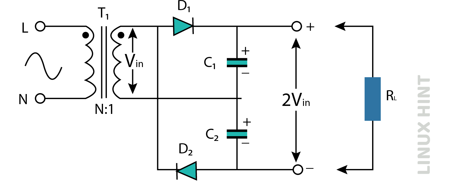
The circuit depicted above is a fundamental symmetrical voltage multiplier circuit composed of two half-wave rectifier circuits. The output voltage of a typical half-wave rectifier can be increased by a predetermined value with the incorporation of an additional diode and capacitor at its output. The structure of this voltage multiplier is commonly referred to as a full wave series multiplier due to the presence of a conducting diode in each half cycle, resembling the operation of a full wave rectifier circuit.
When the input voltage follows a sinusoidal waveform, capacitor C1 gets charged through the conducting diode D1 during the positive half-cycle, while capacitor C2 gets charged through the conducting diode D2 during the negative half-cycle. The voltage output, denoted as 2VIN, is measured across the two capacitors that are linked in series.
Theoretically, a voltage multiplier circuit has the potential to generate an endless voltage. However, because of its limited voltage regulation and low current capacity, these circuits are often designed to amplify the voltage by a factor of less than 10. Nevertheless, when appropriately built in conjunction with an appropriate transformer, voltage multiplier circuits exhibit the capability to generate output voltages ranging from a few hundred to tens of thousands of volts. The specific output voltage achieved is contingent upon the initial input voltage value, while consistently maintaining low currents within the milliamperes range.
Voltage Doubler
The voltage doubler is a circuit configuration that is commonly used in electronic systems to increase the voltage level.
The Voltage Doubler is a type of voltage multiplier circuit that is designed to increase the voltage output by a factor of two. The circuit is composed of a pair of diodes, a duo of capacitors, and an oscillating alternating current (AC) input voltage, with the possibility of utilizing a pulse width modulation (PWM) waveform as well. The diode-capacitor pump circuit is capable of producing a direct current (DC) output voltage that is equivalent to the peak-to-peak amplitude of the sinusoidal input signal. To clarify, the peak voltage value is doubled because of the collaborative operation between the diodes and capacitors, leading to an effective doubling of the voltage.
Working Principle
The DC voltage doubler circuit is a circuit that is designed to double the input voltage. It is used in many electronic devices for increasing voltage levels in various applications.
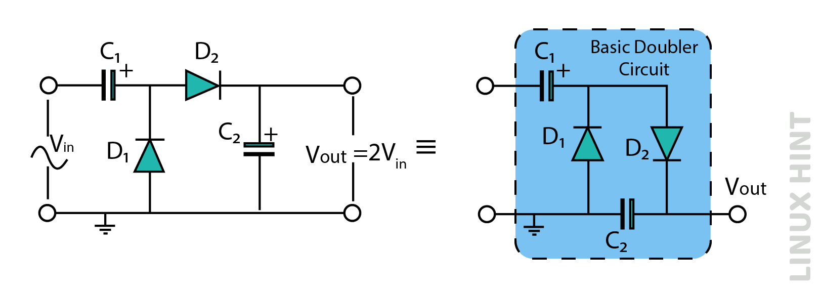
The above diagram shows the configuration of voltage doubler circuit with half-wave rectification. During the negative half of the sinusoidal AC waveform, the diode D1 becomes forward biased and allows the flow of current, resulting in the charging of the pump capacitor, C1, up to the peak input voltage, denoted as Vp. Due to the absence of a discharge channel for capacitor C1, it retains its full charge and functions as a storage component in conjunction with the voltage supply in series. Simultaneously, diode D2 conducts via diode D1, resulting in the charging of capacitor C2.
During the positive half, diode D1 exhibits reverse bias, thereby impeding the discharge process of capacitor C1. Conversely, diode D2 demonstrates forward bias, leading to the charging of capacitor C2. However, due to the presence of a voltage around the capacitor C1 that is already equivalent to the peak voltage, capacitor C2 undergoes charging to a value that is twice the peak input voltage.
During the negative half-cycle, capacitor C1 is charged to the peak input voltage ‘Vp’ by the conducting diode D1. Conversely, during the positive half-cycle, diode D2 adds the AC peak voltage of Vp on the capacitor denoted as C1 and transmits the combined voltage to the capacitor denoted as C2. The discharge of the voltage across capacitor C2 occurs as it is sent through the load in preparation for the subsequent half cycle.
The voltage of the capacitor dentoed as C2 can be determined by the equation Vout = 2Vp, accounting for the voltage drop at the diodes. Here, Vp represents the peak input voltage. It should be noted that the double output voltage mentioned in this context does not exhibit immediate behavior, but rather experiences a gradual increase over each input cycle, ultimately reaching a steady state value of 2Vp.
“Voltage Multiplier Circuits” can generate higher voltages from a low-voltage power source, eliminating the need for a costly high-voltage transformer. This is achieved through the utilization of a voltage doubler circuit, which enables the use of a transformer with a lower step-up ratio compared to what would be required in the case of a conventional full-wave supply. However, it is important to acknowledge that they are only able to provide low currents to high-resistance loads.
DC Voltage Tripler
The DC voltage tripler circuit is a type of electronic circuit that is designed to triple the input voltage. It achieves this by utilizing a combination of diodes and capacitors to generate a voltage output that is three times the magnitude of the input voltage.
By incorporating an extra stage consisting of a single diode and capacitor into the above half-wave voltage doubler circuit, it is possible to construct an alternative voltage multiplier circuit known as a voltage tripler circuit. This circuit effectively amplifies the input voltage by a factor of three.
Working Principle
The voltage tripler circuit consists of one-half stages of voltage doubling. The voltage multiplier circuit described above produces a direct current (DC) output that is equivalent to 3x times the voltage peak value (3Vp) of the sinusoidal input signal. Similar to the voltage doubler circuit discussed before, the diodes included in the voltage tripler circuit facilitate the charging and blocking of capacitor discharge, contingent upon the direction of the input half-cycle. A voltage drop of 1Vp is observed across capacitor C3, whereas capacitor C2 exhibits a voltage drop of 2Vp. Due to the series connection of these capacitors, the load is exposed to an overall voltage of 3Vp.
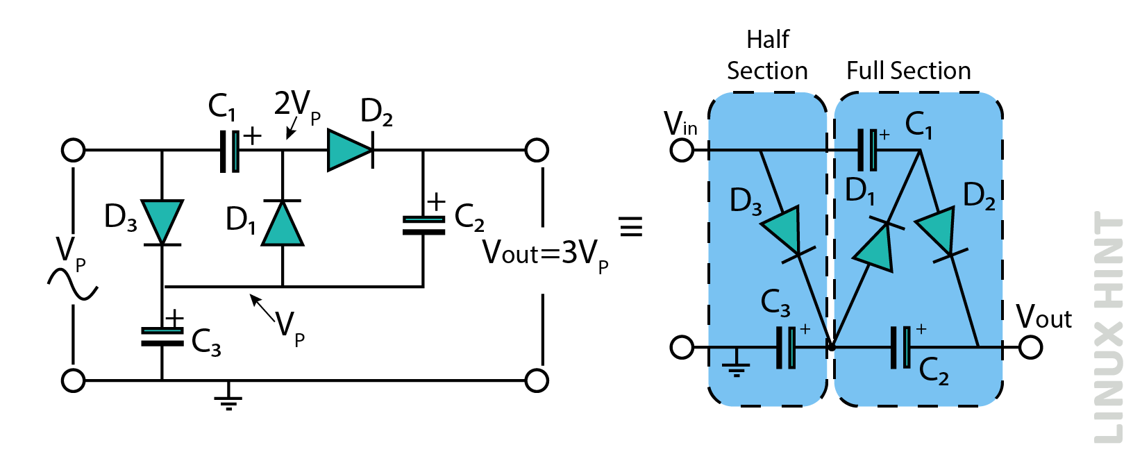
It should be noted that the actual output voltage can be calculated as three times the peak input voltage, taking into account the voltage dips across the diodes, expressed as 3Vp – V(diode).
DC Voltage Quadrupler
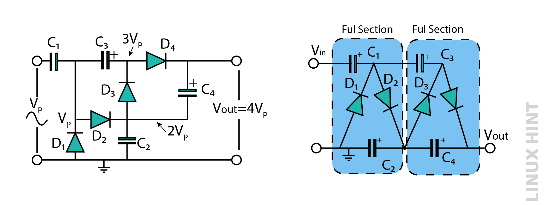
Voltage multipliers are electronic circuits that increase the input voltage of a signal. As a voltage tripler circuit is formed by connecting one and a half voltage multipliers in series, a similar voltage quadrupler circuit can be formed by connecting two complete voltage doubler circuits in series, as depicted below:
The DC voltage quadrupler circuit is a configuration that is designed to increase the input voltage by a factor of four.
Working Principle
The initial voltage multiplier stage amplifies the peak input voltage by a factor of two, while the subsequent stage further amplifies it by another factor of two. As a result, the direct current (DC) output is equivalent to 4x times the peak voltage value (4Vp) of the sinusoidal AC input signal. Additionally, the utilization of capacitors with high capacitance values might contribute to the mitigation of ripple voltage.
It has been observed that Voltage Multipliers are uncomplicated circuits composed of diodes and capacitors that can amplify the input voltage by factors of two, three, or four. By sequentially connecting individual half or full-stage multipliers in a series configuration, the desired DC voltage can be applied to a specific load without necessitating a step-up transformer.
Conclusion
Voltage multipliers and rectifiers share several similarities, as they both serve the purpose of converting AC-to-DC voltages. This conversion is essential for various electrical and electronic circuit applications, including cathode-ray tubes, microwave ovens, high-voltage test equipment, and others. These applications require the generation of a significantly high DC voltage from a comparatively low AC supply.